
A multi-channel arinc429 data transceiver circuit structure developed based on dsp and cpld

A technology for sending and receiving circuits and data sending and receiving, which is applied in the direction of electrical digital data processing and instruments, and can solve problems such as limited DSP circuit functions, loss of multi-channel ARINC429 data reception, and data conflicts.

Active Publication Date: 2017-01-11
BEIHANG UNIV
View PDF4 Cites 0 Cited by
  • Summary
  • Abstract
  • Description
  • Claims
  • Application Information

AI Technical Summary

Problems solved by technology

[0002] At present, the known ARINC429 data transceiver circuit based on DSP and FPGA is composed of DSP circuit, FPGA circuit and ARINC429 bus transceiver chip circuit. Transceiver capability, but multiple channels receive ARINC429 data at the same time, prone to data collision, loss and bit error
The known multi-channel ARINC429 receiving circuit based on DSP and CPLD occupies too many external interrupts of DSP, which makes DSP extremely limited in circuit function, and communication conflicts are prone to occur when multi-channel data is sent and received at the same time, making data processing in DSP In the process, it is easy to lose the reception of multi-channel ARINC429 data

Method used


Image

  • A multi-channel arinc429 data transceiver circuit structure developed based on dsp and cpld
  • A multi-channel arinc429 data transceiver circuit structure developed based on dsp and cpld
  • A multi-channel arinc429 data transceiver circuit structure developed based on dsp and cpld

Examples


Embodiment Construction

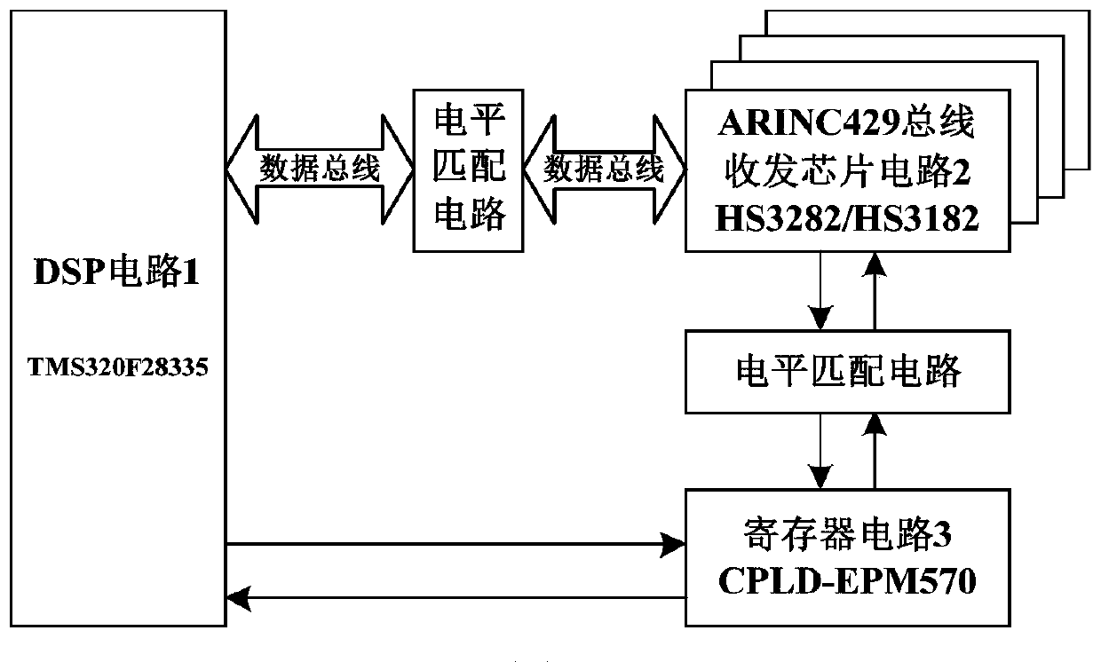
[0023] The present invention will be further described below in conjunction with the accompanying drawings and embodiments. The present invention is described by taking receiving 8-way ARINC429 data and sending 4-way ARINC429 data as an example. All parentheses "(send)" and "(receive)" indicate data and signal direction only.

[0024] exist figure 1 Among them, the connection directions of each functional block diagram and arrow represent the basic circuit principle and signal control relationship of the present invention. The multi-channel ARINC429 data transceiver circuit developed based on DSP and CPLD includes DSP circuit 1, and also includes multiple groups of ARINC429 bus transceiver chip circuits 2 and register circuit 3 realized by CPLD chip programming;

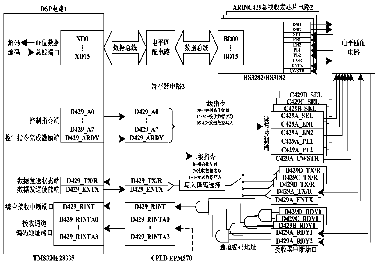
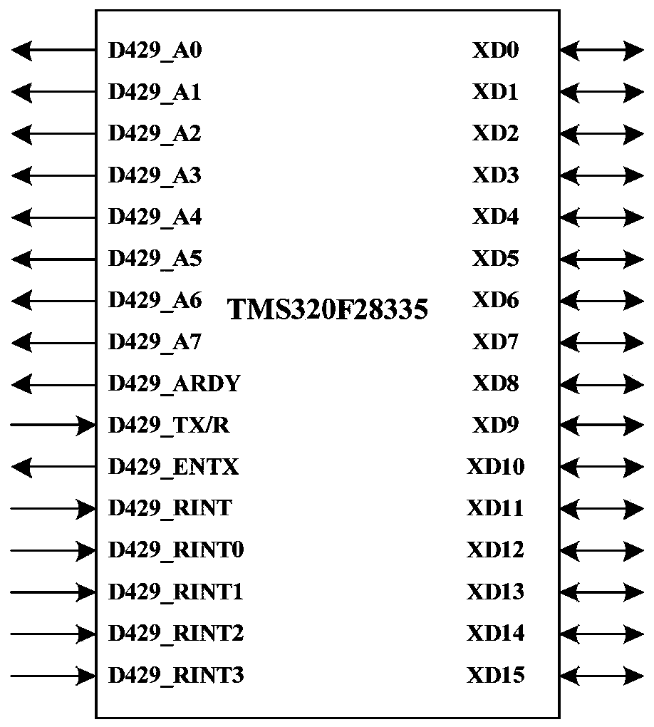
[0025] Attached below figure 2 - attached Figure 4 The present invention is further described.

[0026] The 16-bit data bus XD0~XD15 of the DSP circuit 1 is connected with the data bus BD00~BD15 of the multip...


PUM


Abstract

The invention discloses a multi-way ARINC429 data transmit-receive circuit structure based on the development of a DSP and a CPLD. The multi-way ARINC429 data transmit-receive circuit structure based on the development of the DSP and the CPLD comprises a DSP circuit, multiple sets of ARINC429 bus transmit-receive chip circuits, an auxiliary control circuit achieved through CPLD programming, wherein a data end of each ARINC429 bus transmit-receive chip is connected with the DSP, a control end of each ARINC429 bus transmit-receive chip is connected with the CPLD, the DSP circuit achieves control over the multiple sets of ARINC429 bus transmit-receive chips by sending an control instruction to a register circuit achieved through CPLD chip programming, and receiving decoding and sending coding of ARINC429 data are achieved through software in a DSP chip. The multi-way ARINC429 data transmit-receive circuit structure based on the development of the DSP and the CPLD can achieve real-time reading and sending of multiple ways of ARINC429 data through a data bus of the DSP chip, avoids collision, loss and error codes of the data, and achieves high-speed processing of the data.

Description

technical field [0001] The invention relates to the technical field of ARINC429 data transceiver circuit, in particular to a multi-channel ARINC429 data transceiver circuit structure developed based on DSP and CPLD. Background technique [0002] At present, the known ARINC429 data transceiver circuit based on DSP and FPGA is composed of DSP circuit, FPGA circuit and ARINC429 bus transceiver chip circuit. Transceiver capability, but receiving ARINC429 data from multiple channels at the same time is prone to data collision, loss and bit error. The known multi-channel ARINC429 receiving circuit based on DSP and CPLD occupies too many external interrupts of DSP, which makes DSP extremely limited in circuit function, and communication conflicts are prone to occur when multi-channel data is sent and received at the same time, making data processing in DSP In the process, it is easy to lose the reception of multi-channel ARINC429 data. Contents of the invention [0003] The pre...

Claims


Application Information

Patent Timeline
Patent Type & Authority Patents(China)
IPC IPC(8): G06F13/40G06F13/38
Inventor 王玮陈刚李鹏丁振兴
Owner BEIHANG UNIV
Learn More