Electric locomotive auxiliary engine protection device

A technology for protection devices and electric locomotives, which is applied to emergency protection circuit devices, overcurrent-responsive protection, electrical components, etc., can solve problems such as difficult maintenance, complicated wiring, and low reliability of protection devices, and achieve reduction Effects of mutual interference, simplified wiring, and improved protection strategies

Active Publication Date: 2014-05-28
ZHUZHOU CSR TIMES ELECTRIC CO LTD
View PDF3 Cites 2 Cited by
  • Summary
  • Abstract
  • Description
  • Claims
  • Application Information

AI Technical Summary

Problems solved by technology

[0010] The existing auxiliary equipment protection devices for electric locomotives use analog circuits to sample the current flowing in each auxiliary equipment, the sampling accuracy is low, the system response speed is slow, and it is impossible to fully protect the auxiliary equipment.
At the same time, the existing auxiliary protection device has complex wiring, a large number of wires, and is susceptible to interference, resulting in problems such as low reliability of the protection device and difficult maintenance.
In addition, because the existing auxiliary machine protection device adopts the structure of two control boxes, the cost is expensive, it cannot be controlled centrally, and it is inconvenient to use

Method used


Image

  • Electric locomotive auxiliary engine protection device
  • Electric locomotive auxiliary engine protection device
  • Electric locomotive auxiliary engine protection device

Examples


Embodiment Construction

[0036] The implementation of the present invention will be described in detail below in conjunction with the accompanying drawings and examples, so as to fully understand and implement the process of how to apply technical means to solve technical problems and achieve technical effects in the present invention. It should be noted that, as long as there is no conflict, each embodiment and each feature in each embodiment of the present invention can be combined with each other, and the formed technical solutions are all within the protection scope of the present invention.

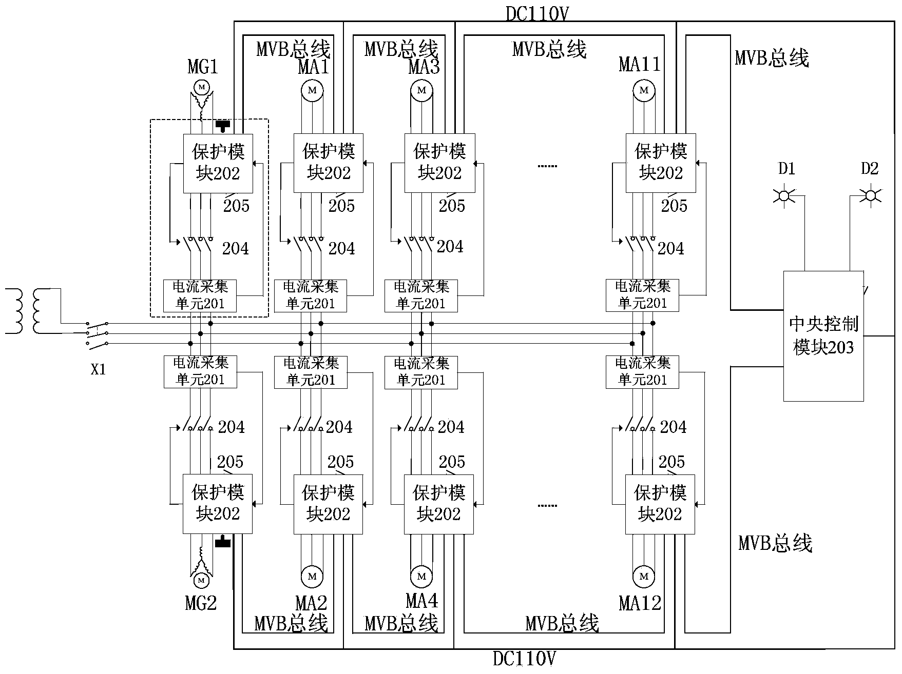
[0037] Aiming at the problems of the existing electric locomotive auxiliary machine protection device, the present invention provides a new type electric locomotive auxiliary machine protection device, its structure diagram is as follows figure 2 shown.

[0038] Such as figure 2 As shown, the electric locomotive auxiliary protection device provided by the present invention includes several current acquisi...


PUM


Abstract

The invention discloses an electric locomotive auxiliary engine protection device which comprises a plurality of current collecting modules, a plurality of auxiliary machine protection modules, a central control module and a plurality of circuit switch units. The current collecting modules are connected with corresponding auxiliary engines to collect the current data of the auxiliary engines. The auxiliary engine protection modules are correspondingly connected with the current collecting modules respectively to compute corresponding electric parameters based on the current data, the central control module analyzes the electric parameters and outputs corresponding control signals, and the auxiliary engine protection modules generate corresponding power source power-on and power-off signals according to the control signals. The circuit switch units are connected in power source circuits of the corresponding auxiliary engines to achieve overcurrent protection on the auxiliary engines. A centralized control strategy is adopted in the device, internal wiring is simplified, mutual interference between components is reduced, the function of degraded running is achieved, the data can be monitored in real time, stored and called, and a user can analyze and maintain the states of the auxiliary engines conveniently.

Description

technical field [0001] The invention relates to the technical field of electric power electronics, in particular to a protection device for an auxiliary machine of an electric locomotive. Background technique [0002] With the rapid development of the national economy, the transportation tasks undertaken by the railway continue to grow. However, for some existing lines, especially the sections with long slopes (such as the section with a slope of 13‰ on the Nankun Line), due to the small capacity of the power supply network at the time of design, with the continuous increase of traction load, most of them are currently in the overloaded state. [0003] When the power supply network is in an overload operation state, the voltage of the power supply network will be at a low level, and the network voltage at the end of the phase-splitting area will even drop below 19kV, which is lower than the lower limit of the working network voltage of the electric locomotive, resulting in ...

Claims


Application Information

Patent Timeline
Patent Type & Authority Applications(China)
IPC IPC(8): H02H7/00H02H3/08
Inventor 郭建罗继光卢学云陈灿张泽华张文辉许倍倍
Owner ZHUZHOU CSR TIMES ELECTRIC CO LTD
Why Eureka
Try Eureka