Assembling workbench for rotor and stator of servo motor

A technology for assembling workbenches and servo motors, which is applied in the direction of electromechanical devices, manufacturing motor generators, electrical components, etc., can solve problems such as motor scratching and abnormal noise, motor temperature rise, and increase motor temperature rise, so as to avoid drooping effect

Inactive Publication Date: 2014-05-28
SHANGHAI FINEPOWER TECH
View PDF5 Cites 14 Cited by
  • Summary
  • Abstract
  • Description
  • Claims
  • Application Information

AI Technical Summary

Problems solved by technology

[0002] In the current permanent magnet AC servo motor, the rotor structure has two types: built-in magnet steel and surface-mounted magnet steel. Because the surface-mounted structure is simple and the workmanship is good, the rotor of the permanent magnet AC servo motor often adopts the surface-mounted structure, which is It is required to strengthen the magnetic steel on the outer surface of the rotor. The current reinforcement method is to wrap a latitude-free belt outside the rotor magnetic steel or to cover the stainless steel ring. The stainless steel ring is relatively simple, but when the motor is working, the stainless steel ring will be induced. The eddy current causes the temperature rise of the motor to increase. Therefore, the surface-mounted rotors usually use winding latitude-free tape to reinforce the magnetic steel; although winding the latitude-free tape can avoid increasing the temperature rise of the motor due to eddy currents, when assembling, due to the fixed The attraction between the rotors, if there is no equipment to ensure the concentricity of the stator and rotor during assembly, the stator core will easily scratch the non-woven belt, which will cause scratching noises when the motor is running, and there will also be magnetic steel falling off, and the motor will fail Hidden dangers

Method used


Image

  • Assembling workbench for rotor and stator of servo motor
  • Assembling workbench for rotor and stator of servo motor

Examples


Embodiment Construction

[0010] The present invention will be described in further detail below in conjunction with the accompanying drawings.

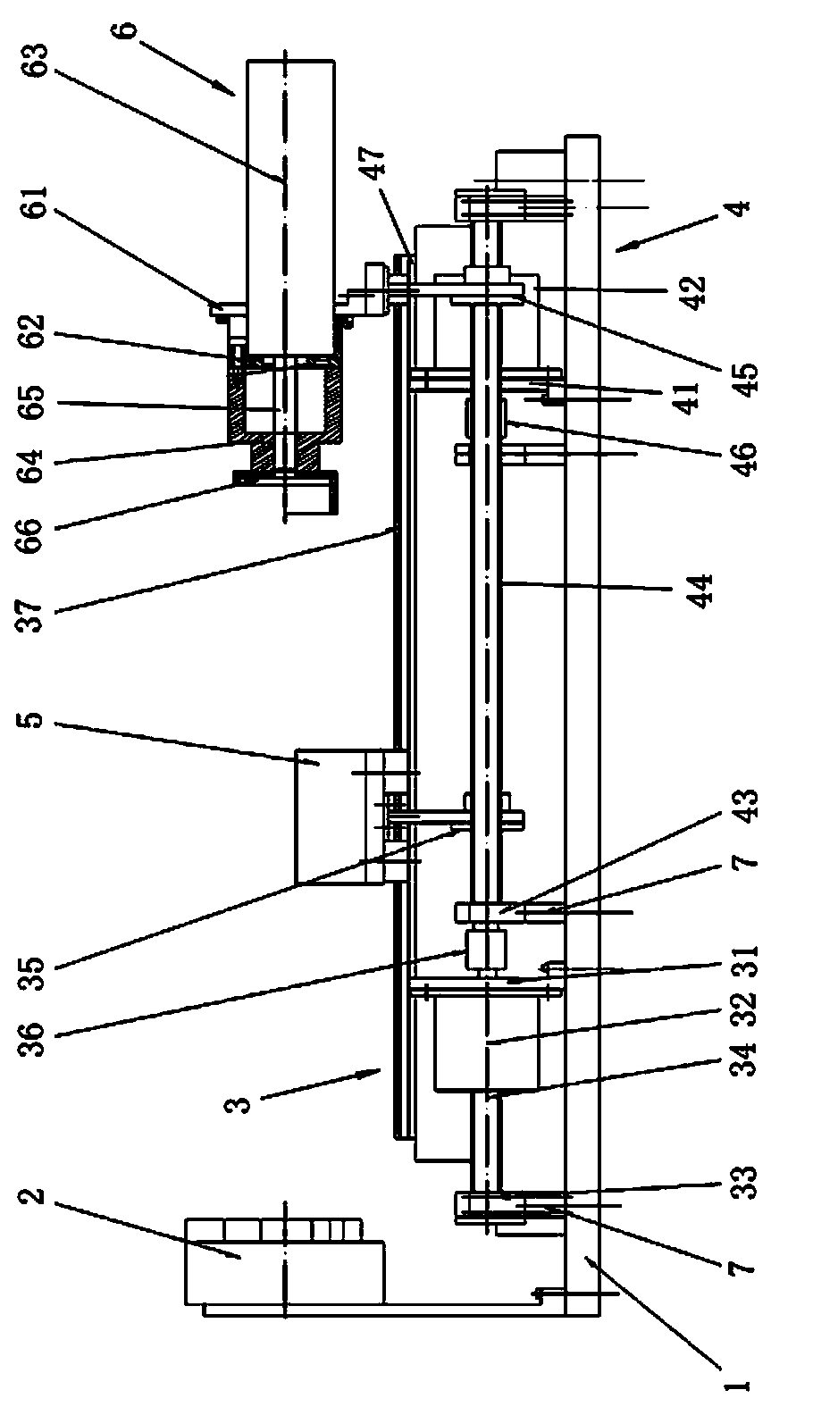
[0011] Such as figure 1 As shown, a servo motor stator and rotor assembly workbench is characterized in that: it includes a base 1, and the base 1 is provided with a rotor three-jaw chuck 2, a stator moving device 3 and a cylinder moving device 4;

[0012] Described stator moving device 3 comprises motor support base 31, motor 32, screw mandrel support base 33, screw mandrel 34, screw mandrel cover 35 and shaft coupling 36, one side of described motor support base 31 is fixed motor 32, and motor supports The upper end of the seat 31 is provided with a slide rail 37; the screw mandrel support seat 33 is located at both ends of the screw mandrel 34, the screw mandrel 34 and the motor 32 are connected by a coupling 36, and the screw mandrel cover 35 is set on the screw mandrel 34;

[0013] Described cylinder moving device 4 comprises motor support base 41, moto...


PUM


Abstract

The invention discloses an assembling workbench for a rotor and a stator of a servo motor. The assembling workbench comprises a base, a rotor three-jaw chunk, a stator moving device and a cylinder moving device are arranged on the base, the stator moving device and the cylinder moving device respectively comprise a motor supporting base, a motor, lead screw supporting bases, a lead screw, a lead screw sleeve and a coupler, the motor is fixed to one side of the motor supporting base, a sliding rail is arranged at the upper end of the motor supporting base, the lead screw supporting bases are located at the two ends of the lead screw, the lead screw is connected with the motor through the coupler, the lead screw is sleeved with the lead screw sleeve, the upper end of the lead screw sleeve of the stator moving device is connected with a stator platform, and the upper end of the lead sleeve of the cylinder moving device is connected with a cylinder assembly. Compared with the prior art, the assembling workbench for the rotor and the stator of the servo motor has the advantages that after the stator is arranged on the platform, the center of the stator is coaxial with the center of the rotor, the rotor is supported through the cylinder and a rotor support, and the rotor is prevented from dropping due to gravity.

Description

technical field [0001] The invention relates to a servo motor stator and rotor assembly workbench. Background technique [0002] In the current permanent magnet AC servo motor, the rotor structure has two types: built-in magnet steel and surface-mounted magnet steel. Because the surface-mounted structure is simple and the workmanship is good, the rotor of the permanent magnet AC servo motor often adopts the surface-mounted structure, which is It is required to strengthen the magnetic steel on the outer surface of the rotor. The current reinforcement method is to wrap a latitude-free belt outside the rotor magnetic steel or to cover the stainless steel ring. The stainless steel ring is relatively simple, but when the motor is working, the stainless steel ring will be induced. The eddy current causes the temperature rise of the motor to increase. Therefore, the surface-mounted rotors usually use winding latitude-free tape to reinforce the magnetic steel; although winding the ...

Claims


Application Information

Patent Timeline
IPC IPC(8): H02K15/00
Inventor 彭兴
Owner SHANGHAI FINEPOWER TECH
Why Eureka
Try Eureka