Vibration generating apparatus

A technology of vibration power generation and induction current, applied in the direction of electromechanical devices, electrical components, etc., can solve the problems of complex structure, difficult implementation, unsatisfactory effect, etc., and achieve the effect of no power generation cost, simple structure, convenient conversion and networking

Inactive Publication Date: 2014-05-28
于遵义 +1
View PDF2 Cites 7 Cited by
  • Summary
  • Abstract
  • Description
  • Claims
  • Application Information

AI Technical Summary

Problems solved by technology

[0003] In order to overcome the complex structure of the existing vibration power generation device, it is not easy to make a high-power power generation device, it is difficult to implement, and the effect is not ideal. The present invention provides a vibration power generation device. Using the power generated by mechanical vibration, the permanent magnet supported by the return spring plate uses its own weight and inertia to convert the vibration into a magnet for corresponding arc-shaped damping oscillation, so that the magnetic lines of force at the two poles of the magnet repeatedly cut the generator coil to generate an induced voltage.

Method used


Image

  • Vibration generating apparatus
  • Vibration generating apparatus
  • Vibration generating apparatus

Examples


Embodiment Construction

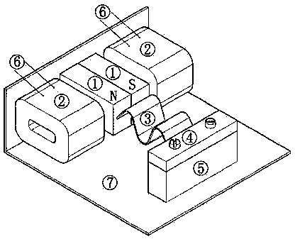
[0013] exist figure 1 In the shown embodiment, the generator coil (2) and bracket (7) are installed on the base (5), the permanent magnet (1) is fixed on the front end of the corrugated spring plate (3), and the corrugated spring plate (3) The rear end of the motor is fixed on the bracket (7) through the fixed pressure plate (4). The permanent magnet (1) relies on its own weight inertia to perform amplified or decelerated oscillations under the vibration of the vibration source, and the permanent magnet (1) performs oscillating motion. At the same time, the generator coils located at both ends of the magnetic poles are continuously cut through the magnetic field lines of the north and south stages, so that the generator coils induce alternating positive and negative alternating voltage currents, and the voltage currents are output through the generator coil lead wires (6);

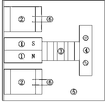
[0014] exist figure 2 In the front sectional view shown, the two generator coils (2) fixed on the bas...


PUM


Abstract

Disclosed is a vibration generating apparatus. A base is provided with two separate generating coils; a permanent magnet capable of free vibration is installed between the two generating coils; there are vibration gaps between the permanent magnet and the generating coils; the permanent magnet is installed at one end of a ripple spring plate; and the permanent magnet can perform vertical reciprocating vibration by taking the ripple spring plate fixed on a support as a radius between the generating coils. When the permanent magnet is subjected to bumpiness or mechanical vibration, the deadweight inertia of the permanent magnet itself enables the permanent magnet to generate vertical oscillation, the oscillation amplitude and the oscillation frequency change with the vibration amplitude and the vibration frequency of a vibration source, the vibrating permanent magnet enables a magnetic line passing through the south pole and the north pole of the permanent magnet to cut the generating coils, and enables induction currents to be generated and be outputted through the lead wires of the generating coils, the induction currents are in sine wave waveforms, and voltages can be transformed and outputted through a transformer so as to facilitate network transmission.

Description

technical field [0001] The invention relates to a power generating device which utilizes the mechanical vibration energy generated by vibration and jolting to generate corresponding mechanical vibrations in the magnets of the generator, so that the magnetic lines of force cut the generating coils to generate voltage and current. Background technique [0002] At present, one of the known vibration power generation devices is to convert the vibration energy into the surface of the piezoelectric ceramic sheet to generate piezoelectric effect power generation; the other is to transmit the vibration to the piezoelectric ceramic sheet to make the piezoelectric ceramic sheet bend The piezoelectric effect is generated to generate electricity; another is to use vibration transmission to move a coil in a magnetic field to generate an induced current. In the above known vibration power generation devices, the first one is piezoelectric effect conversion power generation; the second is ...

Claims


Application Information

Patent Timeline
Patent Type & Authority Applications(China)
IPC IPC(8): H02K35/02
Inventor 于遵义于涛
Owner 于遵义
Why Eureka
Try Eureka