Wheels for flat tires

A technology for flat tires and wheels, which is applied in the direction of wheels, rims, vehicle parts, etc., can solve the problems of support, tire support size limitation, poor use convenience, etc., and achieve the effect of maintaining connection strength, easy use, and reducing steps

Active Publication Date: 2017-07-04
藤本广庆
View PDF20 Cites 0 Cited by
  • Summary
  • Abstract
  • Description
  • Claims
  • Application Information

AI Technical Summary

Problems solved by technology

[0039] The tire support when the tire blows out in the prior art has the following problems: because the tire support part cannot be deformed to the axle side, it will limit the size of the tire support, because there is no shaft in the direction of the axle and a hole for inserting the shaft. Fixed so that the connection strength of the tire supporting parts against external forces in various directions is low, the usability is poor, the gap between the joints between the tire supports is large, and it is difficult to always support the tires, etc.

Method used


Image

  • Wheels for flat tires
  • Wheels for flat tires
  • Wheels for flat tires

Examples


Embodiment

[0158] Below, according to Figure 10 to Figure 23 Examples of the present invention will be described.

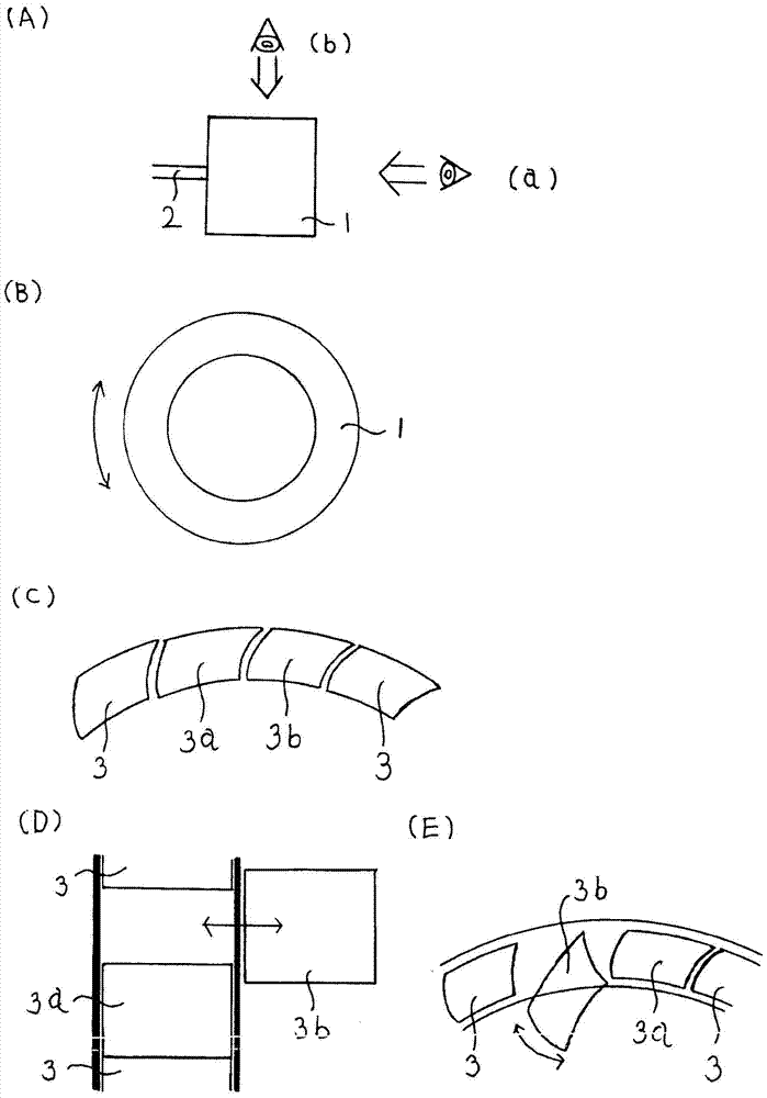
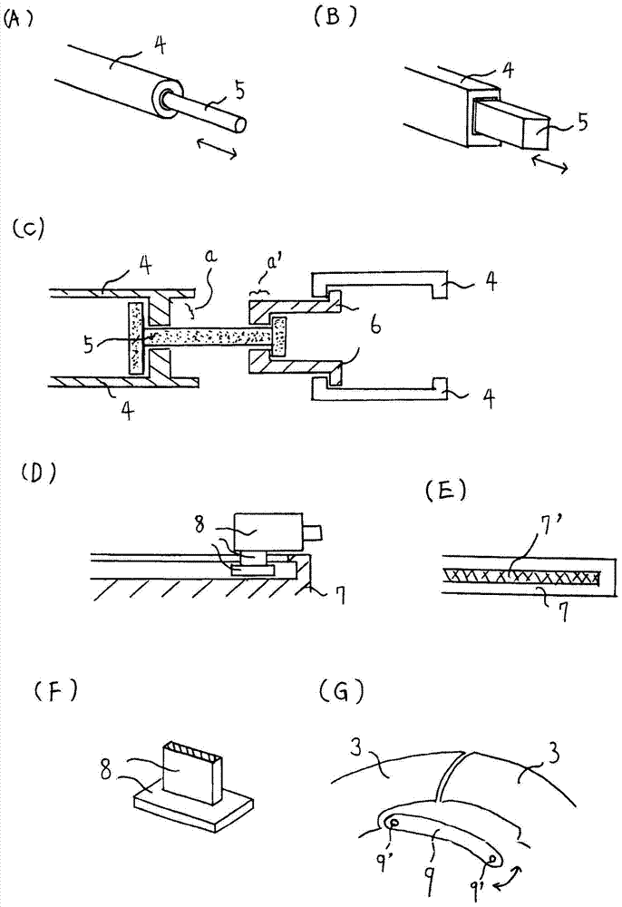
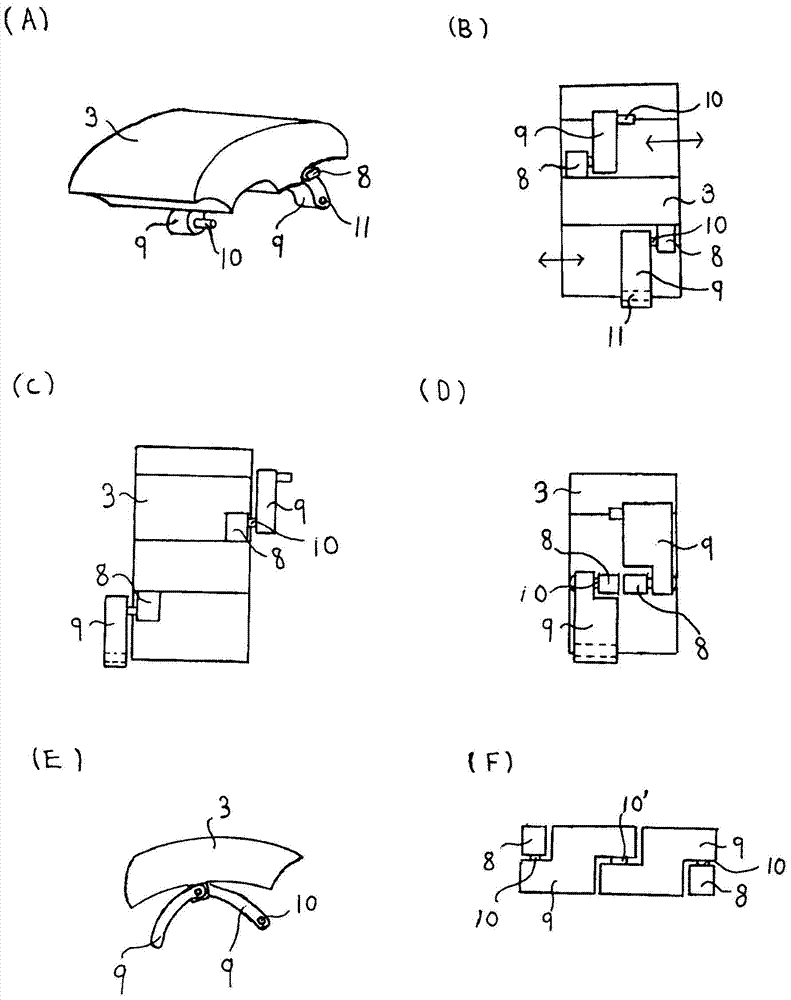
[0159] Figure 10 An example of a schematic view showing a part of the tire support of the present invention, (A) to (F) are cross-sections of one side of the tire support in parallel to the axle when the tire support is viewed from a direction perpendicular to the axle, (G) and (H) are cross-sections of the tire support viewed from a direction perpendicular to the axle, (I) and (J) are views of the tire support viewed from a direction parallel to the axle, (A) to (J) The upper side of the figure is the part in contact with the inner surface of the tire, and the lower side is the axle side, which is the part in contact with the rim.

[0160] Figure 10 (A) is a structure in which the part below the contact part with the tire is cut away, and (B) is a structure in which the part supporting the contact part with the tire in (A) is shifted to one side, ( C) is a structure...


PUM


Abstract

The objective of the tire support during tire puncture of the present invention is the use of the tire support such that the size of a ground-contacting section of the outer diameter of the tire support is close to the size of the outer diameter of the space within the tire, the connection strength of tire support sections is maintained, the use of the tire support is easy, and a level difference resulting from the gap at the joint formed between tire supports is small.

Description

technical field [0001] The present invention relates to a tire blowout countermeasure wheel. Background technique [0002] Regarding the tire blowout countermeasure wheel of the prior art, the following 0003-0017 will be described. [0003] Regarding the tire support when the tire blows out in the space surrounded by the tire and the rim of the Japanese patent 4102981, in the patent 4102981 "embodiment of the invention", it is described that " Figure 6 ...The lower part of 1' near 4 is supported between the left and right sides of 17 with concave and convex convex strip pairs 1' that play a supporting role.... ", it is described in (45) that the supporting structure is supported on the left and right sides of the wheel. [0004] In addition, the "embodiment of the invention" of the patent 4102981 " Figure 6 ..." Afterwards, it is described as "In addition, this wheel is composed of a structure without 12, a ring-shaped structure with one 12, and a structure that functions...

Claims


Application Information

Patent Timeline
Patent Type & Authority Patents(China)
IPC IPC(8): B60C17/04B60B21/12
CPCB60B25/02B60B25/22B60B2900/731B60C17/04B60C17/041
Inventor 藤本广庆
Owner 藤本广庆
Why Eureka
Try Eureka