Method for assembling gearbox components

A technology for connecting components and motor vehicle transmissions, applied to components with teeth, belts/chains/gears, mechanical equipment, etc., can solve the problems of reducing vibration and insufficient, and achieve the effect of high shifting force

Active Publication Date: 2014-05-28
SCHAEFFLER TECH AG & CO KG
View PDF10 Cites 0 Cited by
  • Summary
  • Abstract
  • Description
  • Claims
  • Application Information

AI Technical Summary

Problems solved by technology

Although the complex structure significantly reduces vibration, it is not enough

Method used


Image

  • Method for assembling gearbox components
  • Method for assembling gearbox components
  • Method for assembling gearbox components

Examples


Embodiment Construction

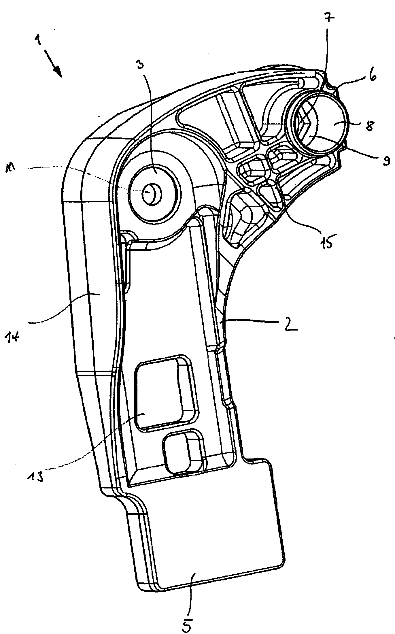
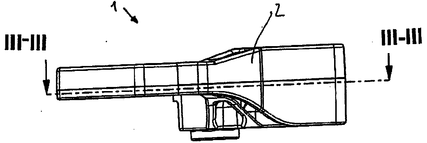
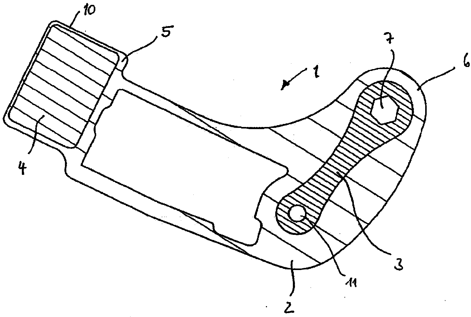
[0031] Figures 1 to 3 A rotating mass 1 for a shift shaft (not shown) of a motor vehicle gear transmission is shown. as from image 3 It can be seen that the rotating mass 1 consists of three individual parts which are fixedly connected to one another: the rotating mass has a boom 2 , a connecting part 3 and a shifting mass 4 , wherein the individual parts 2 , 3 , 4 each consist of different materials.

[0032] The revolving mass 1 has an angular basic shape with two legs, on one leg end 5 of which a shifting mass 4 is arranged and on the other leg end 6 of which a coupling Affiliated institutions7. The coupling mechanism 7 is formed by a generally hexagonal shaped cutout in the connecting piece 3 ( Figure 4). For better guidance of the shifting shaft, the part of the connecting part 3 surrounding the cutout forms a cylindrical head as base 9 and the sleeve 8 connected thereto. Due to the non-circular recess, the pivoting mass 1 can be positioned in a form-fitting and r...


PUM


Abstract

The invention relates to a centrifugal mass (1) of a change-speed gearbox of a motor vehicle, comprising a coupling means (7) for connecting the centrifugal mass (1) to a selector shaft and a cantilever (2) to a switching mass (4), which is arranged at the radially protruding end (5) of the cantilever (2). The cantilever (2) is made of a material that is lighter than the switching mass (4).

Description

technical field [0001] The invention relates to a revolving mass of a motor vehicle transmission having a bearing eye for coupling the revolving mass to a shift shaft, an articulation mechanism for pivoting the revolving mass around the bearing eye and a shifter with metal A cantilever of the gear mass is arranged on a radially protruding end of the cantilever. Background technique [0002] Shifting devices for transmissions, for example for gear transmissions, generally take measures to impinge on the shifting or selection process with a defined selection force or shifting force. In addition to this additional force application, however, the damping of undesired vibrations during the selection or shifting process is also an important aspect when designing the shifting device. [0003] Reference DE 10 2005 062 170 A1 relates to a shift weight for a shift transmission having a configuration device and an additional mass connected at least positively to the configuration devi...

Claims


Application Information

Patent Timeline
Patent Type & Authority Applications(China)
IPC IPC(8): F16H61/24
CPCF16H61/24F16H2061/246
Inventor 克劳斯·克拉默约亨·勒费尔曼
Owner SCHAEFFLER TECH AG & CO KG
Why Eureka
Try Eureka