Position detection device and position detection method
A detection device, the technology of absolute position, applied in the direction of measurement device, measurement distance, mapping and navigation, etc., can solve the problems of unusable, continuous and high-precision detection of position, measurement error, etc.
- Summary
- Abstract
- Description
- Claims
- Application Information
AI Technical Summary
Problems solved by technology
Method used
Image
Examples
no. 1 Embodiment approach
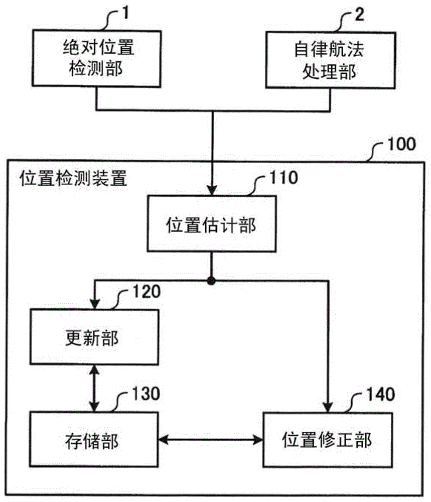
[0023] figure 1 It is a block diagram showing a configuration example of the position detection device according to the first embodiment. Such as figure 1 As shown, the position detection device 100 has: a position estimation unit 110 , an update unit 120 , a storage unit 130 and a position correction unit 140 . In addition, the position detection device 100 obtains an absolute position from the absolute position detection unit 1 and a relative position from the autonomous navigation processing unit 2 . The absolute position detection unit 1 and the autonomous navigation processing unit 2 are included in, for example, a terminal device held by a pedestrian (user) who is a mobile object.
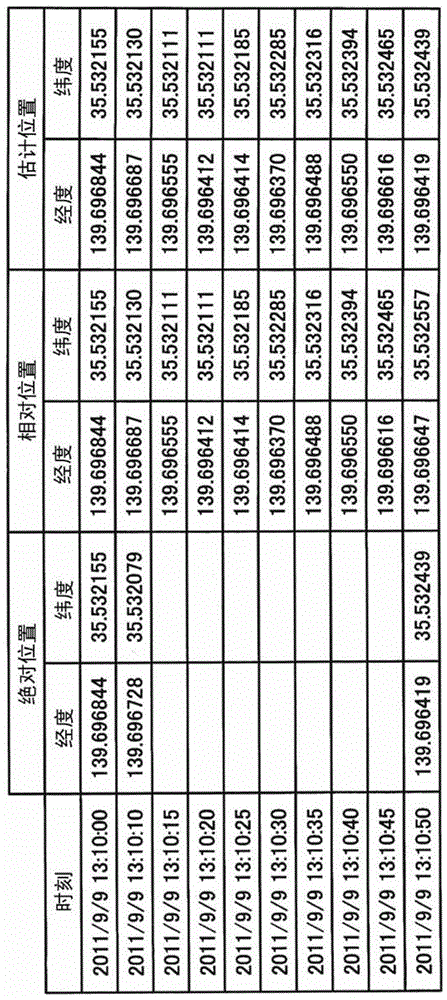
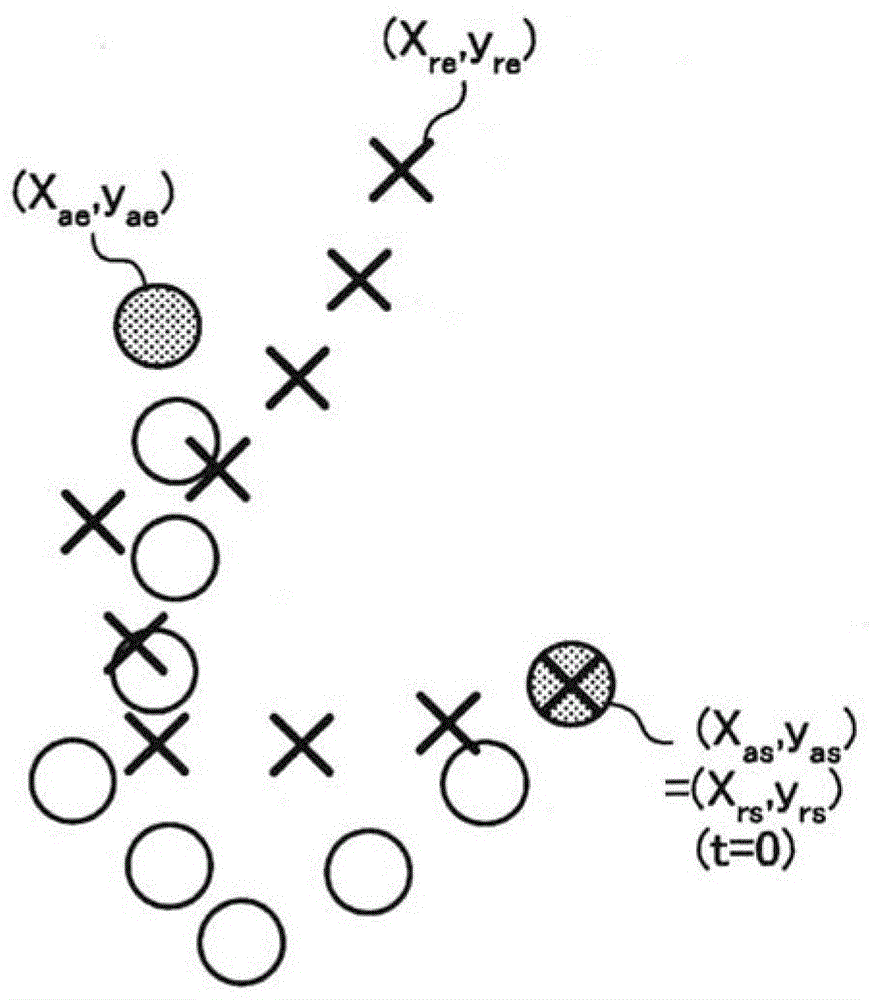
[0024] The absolute position detection unit 1 detects an absolute position using GPS. For example, the absolute position detection unit 1 tries to detect every 5 seconds, and the longitude “X a " and latitude "y a ” is output to the position detection device 100. In addition, in the abso...
no. 2 Embodiment approach
[0110] Figure 8 It is a block diagram showing a configuration example of the position detection device according to the second embodiment. In the second embodiment, the same reference numerals are assigned to the same configurations as those in the first embodiment, and detailed descriptions of the same configurations may be omitted. In the second embodiment, functions, configurations, and processes other than the motion detection unit 3 , the update unit 220 , and the storage unit 230 described below are the same as those in the first embodiment.
[0111] Such as Figure 8 As shown, the position detection device 200 has: a position estimation unit 110 , an update unit 220 , a storage unit 230 and a position correction unit 140 . In addition, the position detection device 200 obtains an absolute position from the absolute position detection unit 1 and a relative position from the autonomous navigation processing unit 2 . In addition, the position detection device 200 acqui...
no. 3 Embodiment approach
[0136] In addition, the embodiment of the position detection device has been described so far, but it can be implemented in various forms other than the above-mentioned embodiment. Therefore, different embodiments will be described with respect to (1) correction parameters, (2) configuration, and (3) program.
[0137] (1) Correction parameters
[0138] In the above-mentioned embodiment, the position correction processing of the estimated position using the correction parameters ie l and θ has been described, but the calculated correction parameters may also be designed as follows: for the step "stepSize(t )" times "l" and adds "θ" to the direction of travel "direction(t)". That is, the calculated correction parameters can be applied at the time point of the output of the autonomous navigation process, and the same result can be obtained.
[0139] (2) Composition
[0140] In addition, information including processing procedures, control procedures, specific names, various da...
PUM
 Abstract
Description
Claims
Application Information
 - R&D
- Intellectual Property
- Life Sciences
- Materials
- Tech Scout
- Unparalleled Data Quality
- Higher Quality Content
- 60% Fewer Hallucinations
Browse by: Latest US Patents, China's latest patents, Technical Efficacy Thesaurus, Application Domain, Technology Topic, Popular Technical Reports.
© 2025 PatSnap. All rights reserved.Legal|Privacy policy|Modern Slavery Act Transparency Statement|Sitemap|About US| Contact US: help@patsnap.com


