Material lifting mechanism

A lifting mechanism and material technology, applied in the field of lifting, can solve the problems of difficulty in ensuring work quality, easy to cause pollution, affecting the yield of finished products, etc., and achieve the effect of facilitating the replacement of materials and cleaning work, improving work stability, and reducing collision strength.

Inactive Publication Date: 2014-06-04
陈哲雄
View PDF0 Cites 0 Cited by
  • Summary
  • Abstract
  • Description
  • Claims
  • Application Information

AI Technical Summary

Problems solved by technology

[0002] At present, in the production process of injection molding products, the feeding methods for injection molding machines mainly include manual feeding, vacuum pumping and large-scale pipe transportation. These traditional production methods have the following shortcomings. First, if the manual feeding method is used, the labor intensity is high. , low efficiency, it is difficult to guarantee the quality of work, it is very easy to affect the rate of finished products due to untimely feeding, it is difficult to form mass production, and it is easy to cause material waste during the feeding process; second, if the vacuum pumping method is used, when replacing materials The process is more troublesome, and it is difficult to clean up all the materials remaining on the vacuum pump, which is easy to form pollution and cause unstable product quality. If the residual materials are colored, the effect will be more obvious; third, if using The large-scale pipeline transportation method has poor flexibility to replace materials, and is not suitable for the use of discontinuous products, which is not conducive to production

Method used


Image

  • Material lifting mechanism
  • Material lifting mechanism
  • Material lifting mechanism

Examples


Embodiment Construction

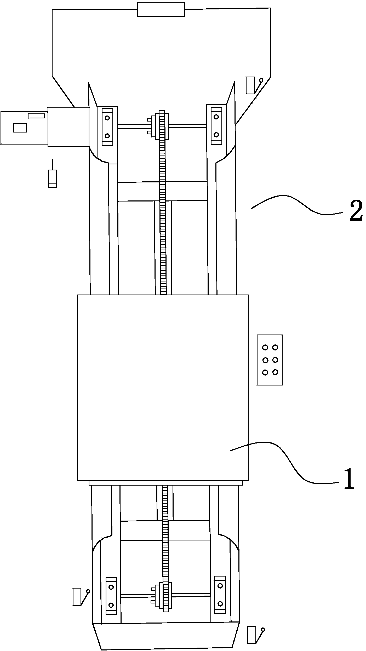
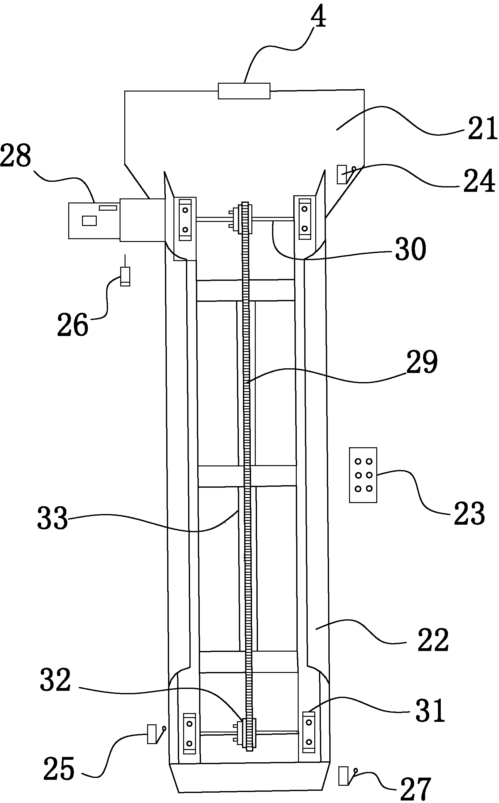
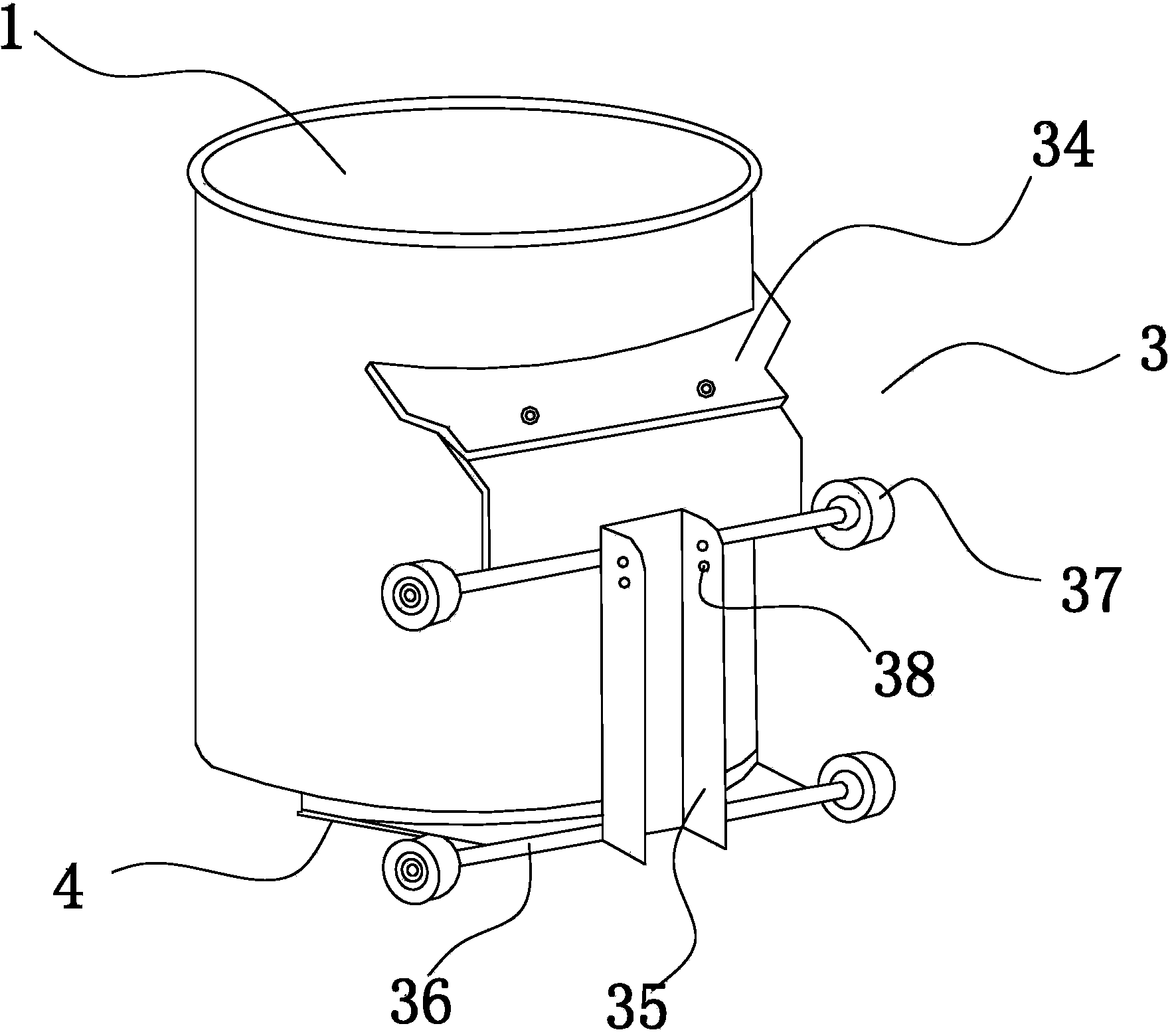
[0024] see Figure 1 to Figure 3 , a material lifting mechanism provided in this embodiment includes a container 1, which also includes a lifting mechanism, and a mounting bracket 3 compatible with the lifting mechanism 2 is fixed on the outer wall of the container 1. There is a lifting mechanism 2, which can automatically transport the container 1 containing the material to a predetermined position accurately and quickly, with high reliability and effectively improves production efficiency; the lifting mechanism 2 includes a vertical support 21, a transmission mechanism and A control assembly for controlling the operation of the transmission mechanism. The transmission mechanism is arranged on the vertical support 21 and parallel to its long side direction, and a guide slide parallel to its transmission direction is arranged symmetrically on both sides of the transmission mechanism. Rail 22. Described control assembly comprises a controller 23 and the upper limit switch 24 t...


PUM


Abstract

The invention discloses a material lifting mechanism which comprises a container, a lifting mechanism and a mounting bracket, wherein the lifting mechanism comprises a vertical support, a transmission mechanism and a control component which controls the transmission mechanism to operate; the transmission mechanism is arranged on the vertical bracket and is parallel to the direction of the long side; guide sliding rails parallel to the transmission direction are respectively arranged on two sides symmetrical to the transmission mechanism. The material lifting mechanism is reasonable in design and high in reliability and is provided with the lifting mechanism, containers filled with materials can be automatically, accurately and rapidly transported to preset positions with high reliability and the production efficiency is effectively improved. Moreover, the material lifting mechanism is provided with a mounting bracket, the containers are easily detached, the flexibility is high, and great convenience is brought to the operations of replacing the materials and cleaning.

Description

technical field [0001] The invention relates to the field of lifting technology, in particular to a material lifting mechanism. Background technique [0002] At present, in the production process of injection molding products, the feeding methods for injection molding machines mainly include manual feeding, vacuum pumping and large-scale pipe transportation. These traditional production methods have the following shortcomings. First, if the manual feeding method is used, the labor intensity is high. , low efficiency, it is difficult to guarantee the quality of work, it is very easy to affect the rate of finished products due to untimely feeding, it is difficult to form mass production, and it is easy to cause material waste during the feeding process; second, if the vacuum pumping method is used, when replacing materials The process is more troublesome, and it is difficult to clean up all the materials remaining on the vacuum pump, which is easy to form pollution and cause u...

Claims


Application Information

Patent Timeline
Patent Type & Authority Applications(China)
IPC IPC(8): B29C45/18
CPCB29C45/18
Inventor 陈哲雄
Owner 陈哲雄
Why Eureka
Try Eureka