Supercharge Your Innovation With Domain-Expert AI Agents!

Laser control device and control method for controlling growth of optical fiber preform core rod

A technology for optical fiber preforms and control devices, applied in manufacturing tools, glass manufacturing equipment, glass deposition furnaces, etc., can solve problems such as laser control methods that are not mentioned, achieve stable growth, improve parameter consistency, and improve optical fiber quality Effect

Active Publication Date: 2016-03-30
ZHONGTIAN TECH ADVANCED MATERIALS CO LTD
View PDF10 Cites 0 Cited by
  • Summary
  • Abstract
  • Description
  • Claims
  • Application Information

AI Technical Summary

Problems solved by technology

[0005] Chinese invention patent 03141875.9 introduces the manufacturing method of the optical fiber preform that reduces the fluctuation of the outer diameter. The spray gun reciprocates at a constant speed relative to the target rod. and other parameters to optimize the system to control the diameter fluctuation, but did not mention the method of laser control

Method used


Image

  • Laser control device and control method for controlling growth of optical fiber preform core rod
  • Laser control device and control method for controlling growth of optical fiber preform core rod
  • Laser control device and control method for controlling growth of optical fiber preform core rod

Examples


Embodiment 1

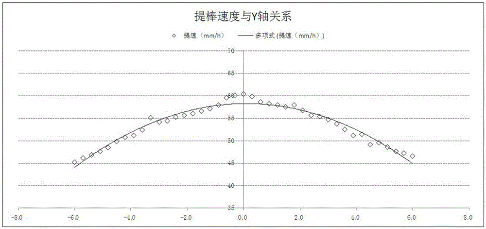
[0046] Embodiment one: Figure 5 The graph at the top of the middle is the comparison of the diameter fluctuation between only the rod lifting speed control mode and the present invention. It can be seen that the mandrel diameter fluctuates within 0.2 mm when using the laser control device of the present invention, and the mandrel diameter fluctuates within 2 mm only using the rod lifting speed control mode.

Embodiment 2

[0047] Embodiment two: Figure 5 The graph in the lower part of the middle is the comparison of the diameter fluctuation between only the torch position movement control mode and the present invention. It can be seen that the mandrel diameter fluctuates within 0.2 mm when using the laser control device of the present invention, and the mandrel diameter fluctuates within 4 mm when only using the blowtorch position movement control mode.

[0048] In the example, the models of selected parts are as follows:

[0049] The laser transmitter is a commercially available Thorlabs H050NL laser transmitter.

[0050] The laser receiver is a commercially available Thorlabs S120C laser receiver.

[0051] The laser power controller is a commercially available Thorlabs PM320 laser power controller.

[0052] The motion controller is a commercially available CONTECCCB-SMC1 type motion controller.

[0053] The motor of the lifting part is a commercially available YASKAWASGMLV-A5ADA6H761 moto...


PUM


Abstract

The invention relates to a laser control device for controlling growth of an optical fiber perform mandril, and a control method thereof. The laser control device comprises a quartz cavity, a laser emitter, a laser receiver, a laser power controller, a signal amplifier I, a signal amplifier II, a motion controller, an industrial personal computer, a PC computer, a lifting part motor, a blowtorch, a blowtorch moving motor and a power supply. The lifting part motor is disposed at an upper part of the quartz cavity; the lifting part motor is connected to a clamping disc; the clamping disc clamps the optical fiber perform mandril; the optical fiber perform mandril is installed in the quartz cavity; the laser emitter and the laser receiver are installed at the lower part of the quartz cavity respectively; the laser receiver is connected to the laser power controller; the laser power controller is connected to the industrial personal computer through the signal amplifier I; the industrial personal computer is connected to the motion controller through the signal amplifier I and the signal amplifier II; the motion controller is connected to the lifting part motor through a control line; the lower part of the quartz cavity is provided with the blowtorch moving motor; and the blowtorch moving motor is provided with the blowtorch.

Description

technical field [0001] The invention relates to a laser control device for controlling the growth of an optical fiber prefabricated rod core rod and its control method, which relates to the manufacture of an optical fiber prefabricated rod core rod that grows uniformly in the axial direction. Apparatus and method for uniform diameter growth. technical background [0002] With the development of optical fiber preform technology, the more mature preform core rod preparation methods mainly include axial vapor deposition (VAD), modified chemical vapor deposition (MCVD), and plasma chemical vapor deposition (MCVD). . The background of the device used in this patent is axial vapor deposition (VAD). [0003] The size of the powder core rod directly affects the main parameters of the optical fiber, such as the refractive index profile and mode field diameter, so the precise control of the uniform diameter of the core rod during the deposition process is of decisive significance to...

Claims


Application Information

Patent Timeline
Patent Type & Authority Patents(China)
IPC IPC(8): C03B37/018
CPCC03B37/0142C03B2207/66C03B2207/70
Inventor 秦钰沈一春钱宜刚
Owner ZHONGTIAN TECH ADVANCED MATERIALS CO LTD
Features
  • R&D
  • Intellectual Property
  • Life Sciences
  • Materials
  • Tech Scout
  • Unparalleled Data Quality
  • Higher Quality Content
  • 60% Fewer Hallucinations
Learn More