Method for monitoring distribution of internal tension of continuous annealing horizontal furnace

A tension distribution, horizontal furnace technology, applied in the direction of furnaces, furnace types, heat treatment furnaces, etc., can solve the problems of large differences in strip speed, large differences in tension at the entrance and exit of furnaces, and large fluctuations in product performance. The effect of automatic control regulation

Active Publication Date: 2014-06-04
BAOSHAN IRON & STEEL CO LTD
View PDF2 Cites 4 Cited by
  • Summary
  • Abstract
  • Description
  • Claims
  • Application Information

AI Technical Summary

Problems solved by technology

[0004] The linear speed of these hundreds of furnace rollers is difficult to keep pace with the strip steel. There are two main reasons: 1. Caused by changes in the diameter of the furnace rollers; The material of the roller is generally carbon in order to withstand high temperature, and it is easy to wear); 2. Because the temperature of the strip steel in different areas of the furnace is different, it is greatly affected by thermal expansion and contraction, and the strip speed varies greatly in different areas
Since the speed of the furnace roll and the speed of the strip steel cannot be synchronized, there is a force between the furnace roll and the steel strip, so that the tension of the strip steel in the furnace and the tension at the furnace inlet and outlet are very different.
Due to the change of tension in the furnace, the performance of the product fluctuates greatly

Method used


Image

  • Method for monitoring distribution of internal tension of continuous annealing horizontal furnace
  • Method for monitoring distribution of internal tension of continuous annealing horizontal furnace
  • Method for monitoring distribution of internal tension of continuous annealing horizontal furnace

Examples


specific Embodiment approach

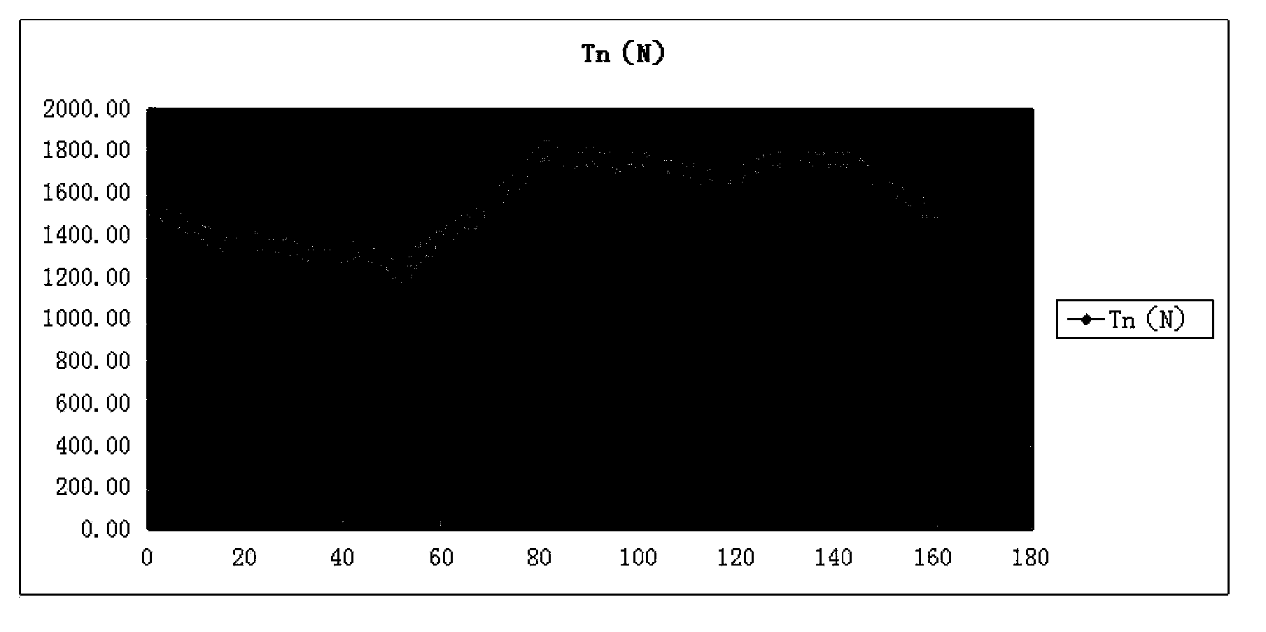
[0056] Taking a continuous annealing horizontal furnace as an example, the tension monitoring in the furnace is carried out:

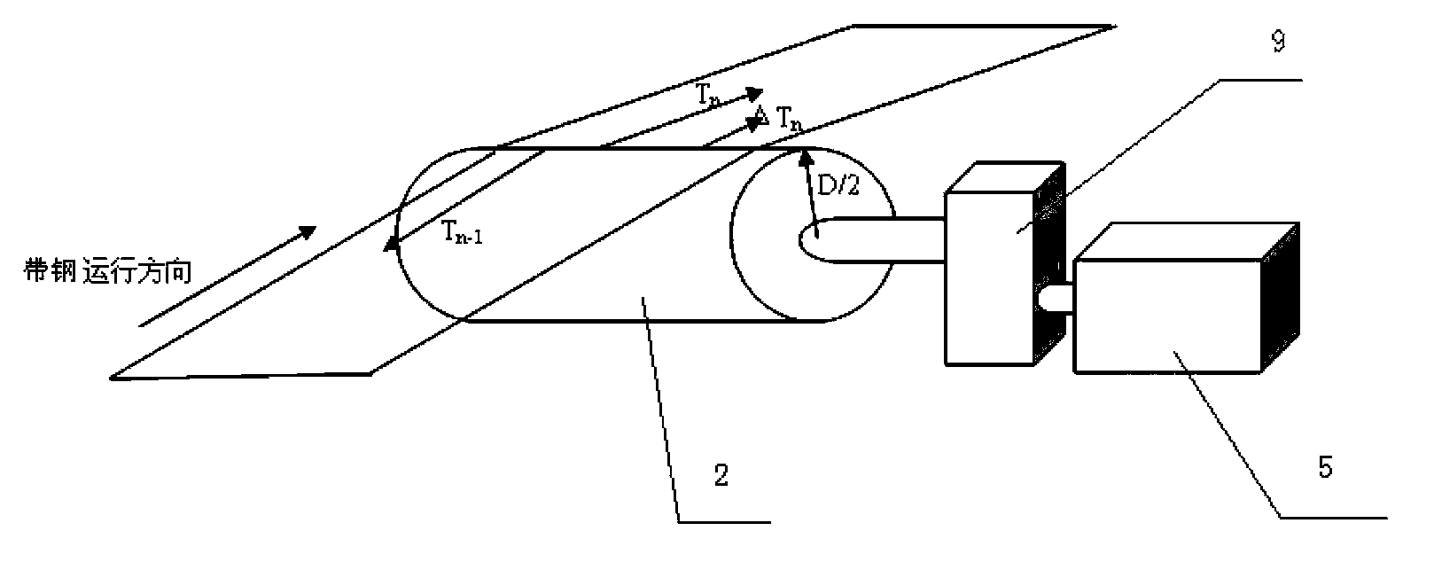
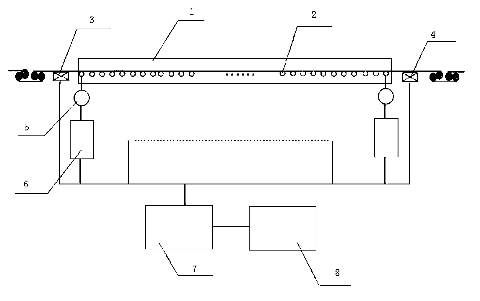
[0057] The furnace has a total of 159 furnace rollers (that is, the n value), and the roller diameter D is 0.18m. Each furnace roller is equipped with a drive motor 5 with a power P=1.5KW, the gear ratio i=6.41, and the rated speed N b is 1420rpm, so the maximum output force of each furnace roller 2 on the roller surface ΔT=(i*9550*P / N b ) / (D / 2)=(6.41*9550*1.5 / 1420) / (0.18 / 2)=718.5N. The entrance tension T of the continuous annealing horizontal furnace measured by the entrance tension measuring device 3 during calculation 入 is 1527N, the exit tension T of the continuous annealing horizontal furnace measured by the exit tension measuring device 4 出 for 1507N.

[0058] The steps to realize it are:

[0059] 1. Measure the no-load load I of each furnace roller during normal production without strip steel Q0n (%) and total no-load load ΣI Q0 And record...


PUM


Abstract

The invention relates to a method for monitoring distribution of internal tension of a continuous annealing horizontal furnace. Idle load of a furnace roller is measured and used as the load under zero output force; in the normal production, the actual load is compared with the idle load, and the difference is the load produced by the acting force of the roller and the strip steel; then load difference is converted into the level of acting force through calculation; and each furnace roller export tension is calculated successively by using the actual tension at the inlet as the benchmark. The method uses the load condition of each furnace roller to calculate the acting force of furnace roller on the strip steel, and uses the tension at the furnace inlet as the benchmark to calculate tension distribution of each point in the furnace. And the results are displayed on the screen, so that production personnel can clearly understand the tension distribution of the strip steel in the furnace, and take corresponding measures to regulate and achieve satisfactory tension distribution in the furnace.

Description

technical field [0001] The invention relates to the field of computer-aided design, which is used in a strip or wire continuous processing furnace, and in particular relates to a method for monitoring tension distribution in a continuous annealing horizontal furnace. Background technique [0002] The strip tension in the furnace section of the continuous annealing horizontal furnace has a great influence on the performance of the strip. Excessive tension in the furnace will cause excessive shrinkage of the strip, and at the same time cause the performance of the strip to decline. Excessive tension will also cause the furnace roll Wear is accelerated. Of course, if the tension in the furnace is too small, it will also cause the strip steel to deviate and break the strip, etc., which will affect the passing of the plate. [0003] At present, the tension measurement of the continuous annealing horizontal furnace is obtained by the tensiometer installed at the entrance and exit...

Claims


Application Information

Patent Timeline
IPC IPC(8): C21D9/56C21D11/00B65H26/04
Inventor 顾华中陈晨
Owner BAOSHAN IRON & STEEL CO LTD
Why Eureka
Try Eureka