High-pressure grout stopping device for L-shaped drill hole ground pre-grouting

A pre-grouting, ground technology, used in earth-moving drilling, wellbore/well components, sealing/packing, etc., can solve problems such as inability to unplug, in-hole accidents, etc.

Inactive Publication Date: 2014-06-04
BEIJING CHINA COAL MINE ENG CO LTD
View PDF5 Cites 2 Cited by
  • Summary
  • Abstract
  • Description
  • Claims
  • Application Information

AI Technical Summary

Problems solved by technology

[0002] With the wide application of wellbore ground pre-grouting technology, L-shaped drilling ground pre-grouting technology has emerged, which combines ground pre-grouting technology with directional drilling technology to grout water blocking or reinforcement for underground horizontal roadways; At present, the grout stop equipment used in the ground pre-grouting project is mainly the slip stop grout plug, which has a simple structure and is easy to operate. It is difficult to effectively transmit the downward impact force of the horizontal section and the horizontal section to the slurry stop equipment, which will lead to the inability to unblock and cause accidents in the hole. Therefore, it is necessary to study new slurry stop equipment to solve the problem of high pressure slurry stop in the deflection section and horizontal section of L-shaped drilling

Method used


Image

  • High-pressure grout stopping device for L-shaped drill hole ground pre-grouting
  • High-pressure grout stopping device for L-shaped drill hole ground pre-grouting
  • High-pressure grout stopping device for L-shaped drill hole ground pre-grouting

Examples


Embodiment Construction

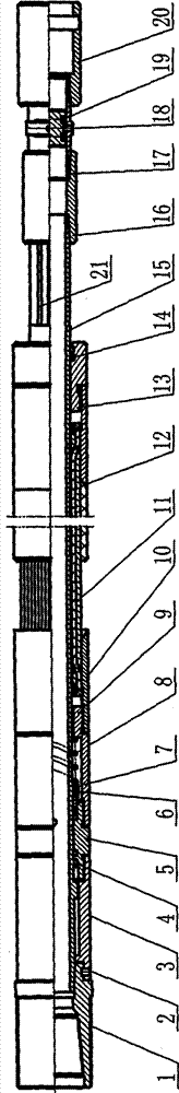
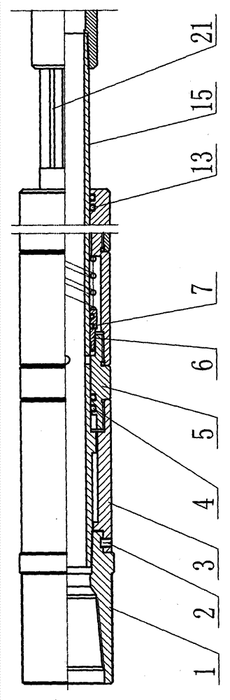
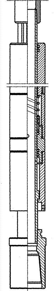
[0015] Such as figure 1 As shown, the L-shaped ground pre-grouting high-pressure grouting equipment for drilling in this embodiment includes a central pipe 15, a rubber cartridge assembly 11 and a blind plugging mechanism for blocking the lower end of the central pipe 15. The rubber cartridge The assembly 11 is set on the central tube 15, and a closed ring cavity is formed between the inner wall of the rubber cartridge assembly 11 and the outer surface of the central tube 15; There is a liquid inlet hole in fluid communication with the hollow tube hole of the central pipe 15, and the fluid communication between the closed ring chamber and the liquid inlet hole is through a one-way fluid conduction mechanism, and the one-way fluid conduction The passage mechanism is opened under the action of the fluid pressure in the hollow pipe hole, so that the fluid in the hollow pipe hole enters the closed ring cavity through the liquid inlet hole and the one-way fluid conduction mechanism...


PUM


Abstract

The invention relates to a high-pressure grout stopping device for L-shaped drill hole ground pre-grouting. The high-pressure grout stopping device comprises a center pipe, a rubber barrel assembly and a blind blocking mechanism used for blocking a pipe opening in the lower end of the center pipe. The center pipe is sleeved with the rubber barrel assembly. A sealed annular cavity is formed between the inner wall of the rubber barrel assembly and the outer surface of the pipe wall of the center pipe. The pipe wall of the center pipe is provided with a liquid inlet hole communicated with hollow pipe hole fluid of the center pipe, the sealed annular cavity and the liquid inlet hole are in fluid communication through a one-way fluid communication mechanism which is opened through the action of pressure of the fluid in a hollow pipe hole, the fluid in the hollow pipe hole enters the sealed annular cavity through the liquid inlet hole and the one-way fluid communication mechanism, and the rubber barrel assembly is expanded through the action of the pressure of the fluid in the sealed annular cavity. The blind blocking mechanism opens the pipe opening in the lower end of the center pipe through the action of pressure of the fluid in the hollow pipe hole. The outer surface of the lower end of the center pipe is provided with a pressure relief groove. The high-pressure grout stopping device overcomes the defects that an existing grout stopping device cannot meet the requirement for successful grout stopping in a large-vertex-angle drill hole or a horizontal drill hole (an L-shaped drill hole).

Description

technical field [0001] The invention relates to a grout stop equipment, in particular to a high-pressure grout stop equipment for L-shaped drilling ground pre-grouting and high-pressure grout stop equipment that can realize high-pressure grout stop in large apex-angle boreholes and horizontal holes (L holes). Background technique [0002] With the wide application of wellbore ground pre-grouting technology, L-shaped drilling ground pre-grouting technology has emerged, which combines ground pre-grouting technology with directional drilling technology to grout water blocking or reinforcement for underground horizontal roadways; At present, the grout stop equipment used in the ground pre-grouting project is mainly the slip stop grout plug, which has a simple structure and is easy to operate. It is difficult to effectively transmit the downward impact force of the horizontal section and the horizontal section to the slurry stop equipment, which will lead to the inability to unbl...

Claims


Application Information

Patent Timeline
IPC IPC(8): E21B33/13
Inventor 安许良刘书杰冯旭海高晓耕李生生王志晓吴莹陈慧贺宏伟籍晓龙陈远坤魏玉怀蒋桂模杨道召
Owner BEIJING CHINA COAL MINE ENG CO LTD
Why Eureka
Try Eureka