Planar torsion spring of flexible joint

A technology of planar torsion springs and flexible joints, applied in the field of robotics, can solve the problems of small maximum relative rotation angle and small external force torque, and achieve the effect of improving reliability and good performance parameters

Active Publication Date: 2014-06-04
ZHEJIANG UNIV
View PDF7 Cites 32 Cited by
  • Summary
  • Abstract
  • Description
  • Claims
  • Application Information

AI Technical Summary

Problems solved by technology

It solves the problem that the maximum external force torque of the existing planar torsion spring is small and the maximum relative rotation angle is small

Method used


Image

  • Planar torsion spring of flexible joint
  • Planar torsion spring of flexible joint
  • Planar torsion spring of flexible joint

Examples


Embodiment 1

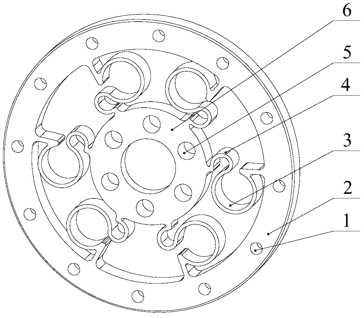
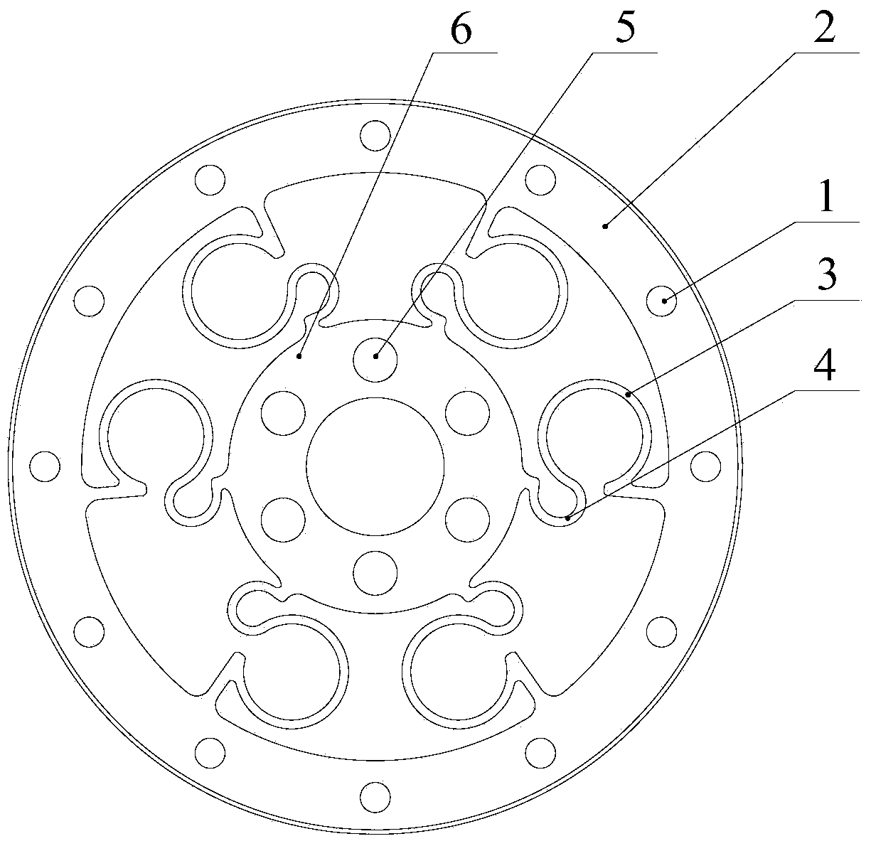
[0029] Such as figure 1 , 2 As shown, a planar torsion spring of a flexible joint includes an inner ring 6, an outer ring 2, and three elastic body units fixed between the inner ring and the outer ring, and each elastic body unit is composed of two symmetrical elastic bodies , each elastomer has two arc segments. In the same elastic body, the openings of the two arc segments are opposite to each other, and both arc segments are superior arcs, wherein the arc segment fixed to the outer ring is the outer elastic arc piece 3, and the arc segment fixed to the inner ring is The segment is the inner elastic arc 4, and the outer elastic arc and the inner elastic arc are tangent to each other in the same elastic body. The ratio of the radius of the outer elastic arc to the radius of the inner elastic arc is:

[0030] 1:10~10:1, according to different application occasions, the plane torsion spring with different performance can be obtained by changing the radius ratio. In order to...

Embodiment 2

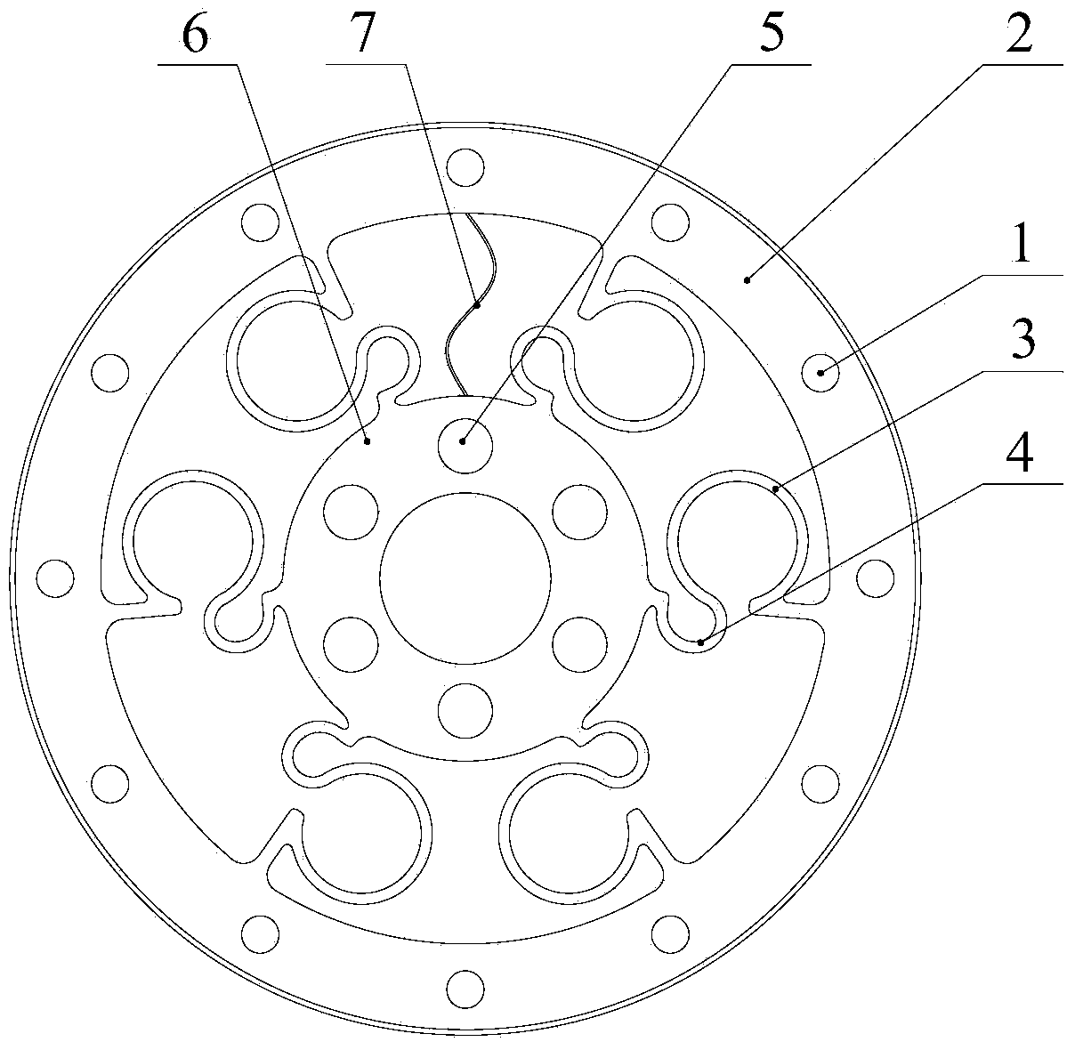
[0050] Such as image 3 As shown, a planar torsion spring of a flexible joint, this embodiment adds a limit lock 7 on the basis of Embodiment 1. One end of the spacer cable 7 is fixed to the outer ring, and the other end is fixed to the inner ring. When the outer ring and the inner ring rotate to a certain position, the spacer cable is straightened to limit the further relative rotation of the outer ring and the inner ring to prevent excessive torque. When it is large, it will damage the plane torsion spring, and the limit cable plays the role of limit protection.

[0051] The limiting cable 7 can be arranged between two adjacent elastic body units or between two elastic bodies of the elastic body unit. There can be one or more limit cables.

Embodiment 3

[0053] Such as Figure 6 As shown, a planar torsion spring of a flexible joint, the difference between this embodiment and Embodiment 1 is that the ratio of the radius of the outer elastic arc to the radius of the inner elastic arc is 1:0.61.

[0054] Through the simulation software, the maximum torque of this embodiment is 8.92 N·m, and the maximum deformation angle is 3.01°. Through the simulation, it can be seen that by changing the ratio of the radius of the outer elastic arc to the radius of the inner elastic arc, different external force torques and deformation angles can be obtained, which can be selected according to different requirements of robot joints. And the performance of the plane torsion spring is better than other torsion springs in the past.


PUM


Abstract

The invention discloses a planar torsion spring of a flexible joint. The planar torsion spring of the flexible joint comprises an inner ring, an outer ring and a plurality of elastic body units fixed between the inner ring and the outer ring, wherein each elastic body unit is composed of two symmetrical elastic bodies, each elastic body is provided with two arc sections, openings of the two arc sections in the same elastic body are opposite, and limiting cables used for limiting a limit rotation angle are arranged between the outer ring and the inner ring. The openings of the two arc sections in the same elastic body are opposite so that the elastic body can have better performance parameters, and the maximum torque value and the relative rotation angle of the inner ring and the outer ring under the torque are both largely improved. The relative rotation angle of the inner ring and the outer ring is limited through the limiting cables, and therefore the planar torsion spring is protected, and the reliability of the planar torsion spring is improved.

Description

technical field [0001] The invention belongs to the technical field of robots and relates to a planar torsion spring of a flexible joint. Background technique [0002] Since the first industrial robot came out in the 1960s, it has played an important role in promoting the development of manufacturing industry. After nearly 60 years of development, industrial robot technology has matured and has been widely used in many fields. However, the intelligence level of industrial robots is relatively low at present. An important reason is the safety issues in the actual industrial production process. Industrial robots and operators must be physically separated. This method ensures the personal safety of operators during the production process, but it cannot improve the efficiency of operations through human-machine collaboration. Therefore, breaking through the bottleneck of safe interaction between industrial robots and humans and the environment is the only way to realize the in...

Claims


Application Information

Patent Timeline
Patent Type & Authority Applications(China)
IPC IPC(8): F16F1/02B25J17/00
Inventor 林群祐朱秋国熊蓉李祖圣
Owner ZHEJIANG UNIV
Why Eureka
Try Eureka