
Sintering area device of solar cell sintering furnace

A solar cell and sintering zone technology, applied in furnaces, furnace types, lighting and heating equipment, etc., can solve the problems of easy temperature crossover, affecting sintering quality, unfavorable temperature zone division, etc., to prevent mutual temperature crossover and ensure sintering. quality effect

Inactive Publication Date: 2014-06-04
XIAN DAYU PHOTOELECTRIC TECH
View PDF0 Cites 1 Cited by
  • Summary
  • Abstract
  • Description
  • Claims
  • Application Information

AI Technical Summary

Problems solved by technology

[0003] The sintering furnace is generally divided into a drying area, a sintering area and a cooling area. The design of the furnace in the sintering area of ​​the existing sintering furnace is similar to that of the traditional tunnel furnace. The entire furnace is similar to the box structure, which is not conducive to the division of the temperature zone. It is easy to cross temperature between different temperature zones, which will affect the sintering quality

Method used


Image

  • Sintering area device of solar cell sintering furnace
  • Sintering area device of solar cell sintering furnace

Examples


specific Embodiment approach

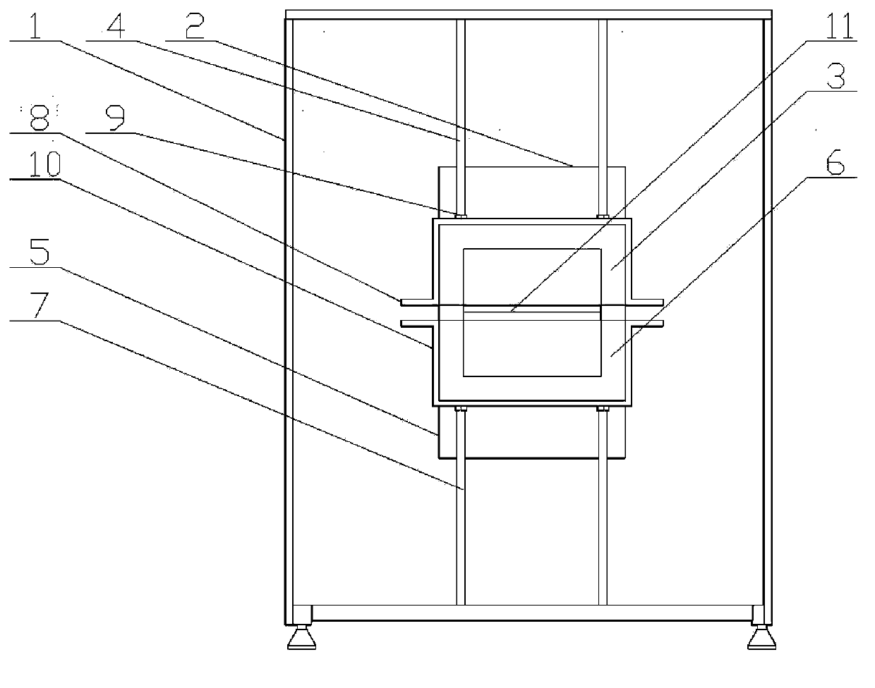
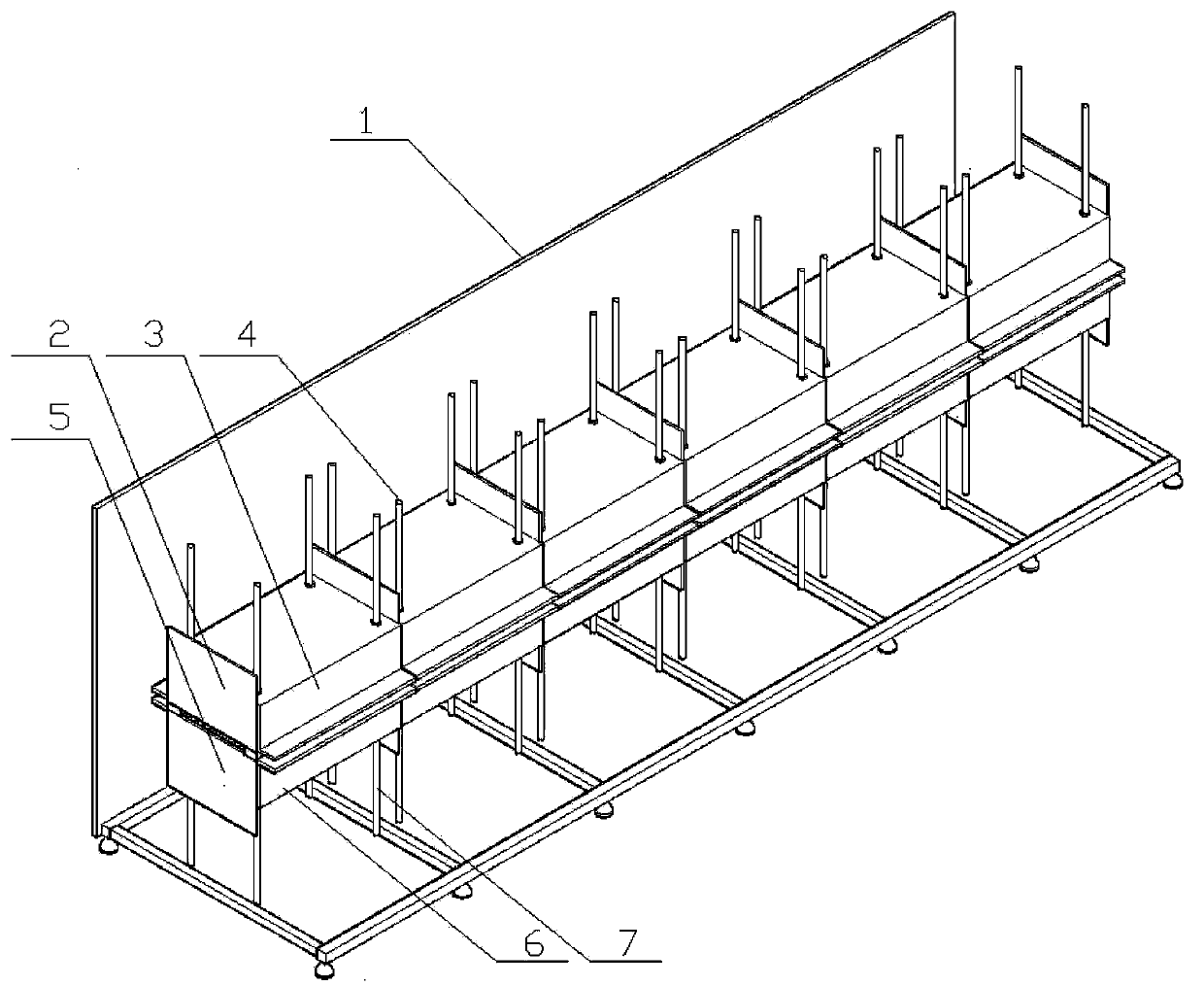
[0017] Such as figure 1 , figure 2 As shown, it shows an embodiment of the present invention, the sintering area device of the solar cell sheet sintering furnace of the present invention, including the transmission mesh belt 11 used to transport the solar cells to be sintered throughout the sintering furnace; and the sintering area frame 1. The frame 1 of the sintering area is composed of stainless steel square tubes, and the outside of the frame composed of stainless steel square tubes is fixed with stainless steel door panels;

[0018] An upper furnace 3 is arranged above the transmission mesh belt 11, and the upper furnace 3 is concave as a whole, and an upper buckle plate 8 is fixedly installed on the outside of the upper furnace 3, and an upper pull rod 4 is fixedly installed on the upper surface of the upper buckle plate 8 by fastening bolts 9. The pull rod 4 is vertically arranged, and its top end is fixedly connected to the inner top plate of the frame 1 in the sinte...


PUM


Abstract

The invention provides a sintering area device of a solar cell sintering furnace. The sintering area device comprises a conveying mesh belt and a sintering area frame, an upper hearth is arranged above the conveying mesh belt, the upper hearth is overall concave, an upper pinch plate is fixedly arranged outside the upper hearth, upper pull rods are fixedly arranged on the upper surface of the upper pin plate through fastening bolts, the upper pull rods are vertically arranged, and the top ends of the upper pull rods are fixedly connected to a top plate inside the sintering area frame. A lower hearth is arranged below the conveying mesh belt and is symmetric with the upper hearth, a lower pin plate is arranged outside the lower hearth, lower supporting rods are fixedly arranged on the bottom face of the lower pin plate through fastening bolts, the lower supporting rods are vertically arranged, and the bottom ends of the lower supporting rods are fixedly connected to a bottom plate inside the sintering area frame. The upper hearth and the lower hearth form a sintering hearth body, the sintering hearth body is divided into six temperature areas in the length direction of the conveying mesh belt, the upper hearth is separated through upper separating plates between different temperature areas, the lower hearth is separated through lower separating plates, and the connecting positions of the separating plates and the upper hearth and the lower hearth are sealed through high temperature resistant sealants.

Description

technical field [0001] The invention relates to production equipment of solar cells, and is specifically applied to the sintering of solar cells. Background technique [0002] With the popularity of solar cell power generation, the demand for solar cells has increased. As an important equipment for the production of solar cells, the demand and usage of solar cell sintering furnaces are also increasing. Solar cell sintering furnaces often take several months to realize Trouble-free operation, so the power consumption of the sintering furnace is quite large, which is mainly reflected in the heating of the temperature zone by the heating tube. [0003] The sintering furnace is generally divided into a drying area, a sintering area and a cooling area. The design of the furnace in the sintering area of ​​the existing sintering furnace is similar to that of the traditional tunnel furnace. The entire furnace is similar to the box structure, which is not conducive to the division of...

Claims


Application Information

Patent Timeline
Patent Type & Authority Applications(China)
IPC IPC(8): F27B9/30
Inventor 周良张超
Owner XIAN DAYU PHOTOELECTRIC TECH
Learn More