
Liquid Crystal Display Device

Inactive Publication Date: 2008-12-11
PANASONIC LIQUID CRYSTAL DISPLAY CO LTD +1
View PDF3 Cites 34 Cited by
  • Summary
  • Abstract
  • Description
  • Claims
  • Application Information

AI Technical Summary

Benefits of technology

[0015]In view of the foregoing circumstances, it is an object of the present invention to prevent cross-talk due to coupling noise to the counter electrode generated in AC driving of a video voltage in the liquid crystal display panel, and to prevent deterioration in display quality of a displayed image on the liquid crystal display panel.
[0026]According to the invention, in a large-size high-definition liquid crystal display panel, it is possible to prevent cross-talk due to coupling noise to the counter electrode generated in AC driving of a video voltage, and to prevent deterioration in display quality of a displayed image on the liquid crystal display panel.

Problems solved by technology

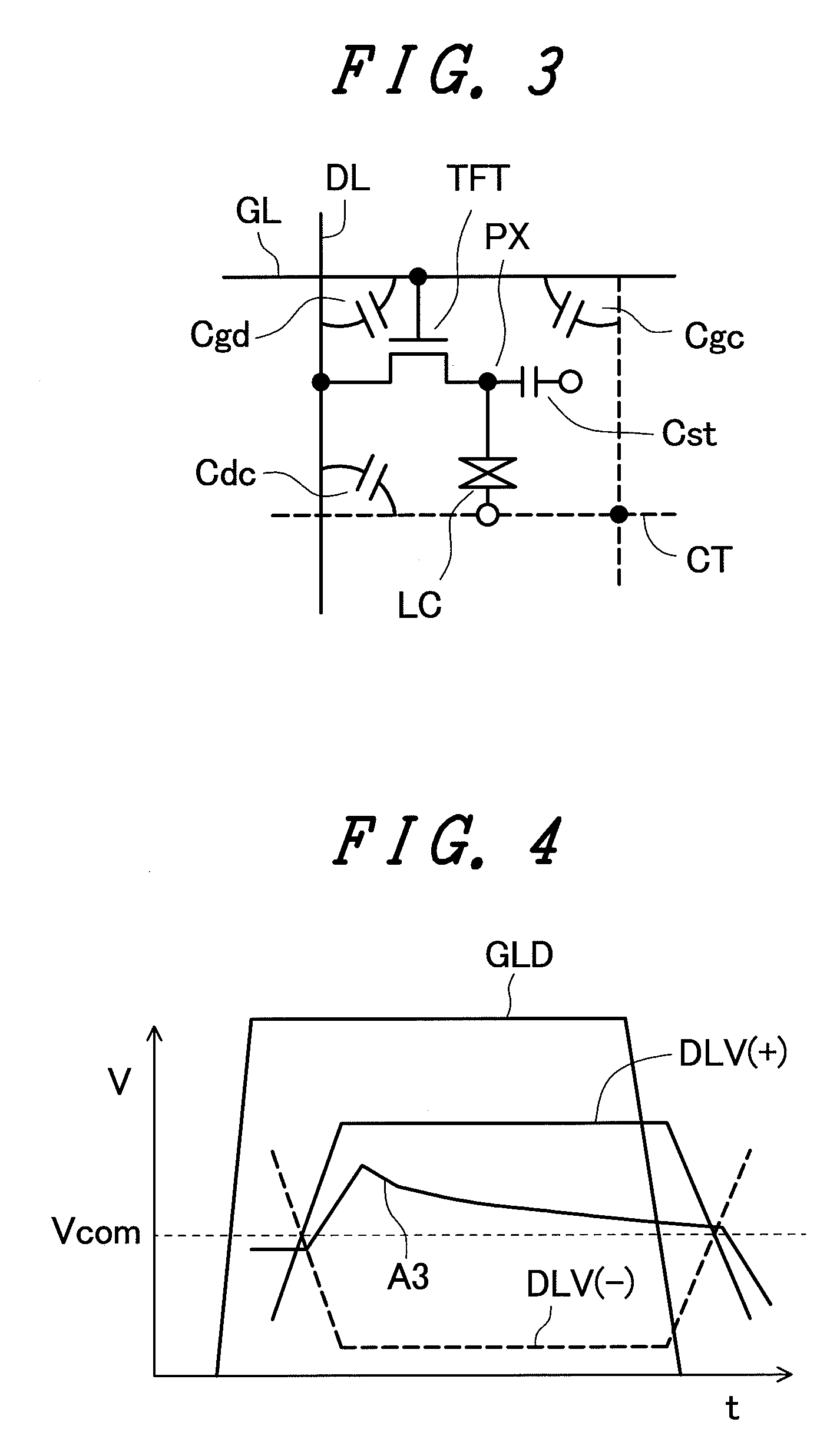
Also, as the liquid crystal panel increases in size, the resistance component from a counter voltage supply source that supplies a counter voltage to the counter electrode cannot be ignored and a problem arises that there a greater difference in coupling noise due to change in the video lines between the near end and far end of the counter voltage supply source.
However, simply supplying the counter electrode with an inverting signal of a voltage change in the counter electrode detected from a specified part, as disclosed in JP-A-6-186530, not only causes occurrence of chrominance non-uniformity on the liquid crystal display panel that is dependent on the distance from the counter voltage supply source, but also causes deterioration in image quality due to cross-talk and so on.

Method used


Image

  • Liquid Crystal Display Device
  • Liquid Crystal Display Device
  • Liquid Crystal Display Device

Examples


Embodiment Construction

[0037]Hereinafter, an embodiment of the invention will be described in detail with reference to the drawings.

[0038]In all the drawings for explaining the embodiment, parts and units having the same functions are denoted by the same reference numerals and their description will be repeated.

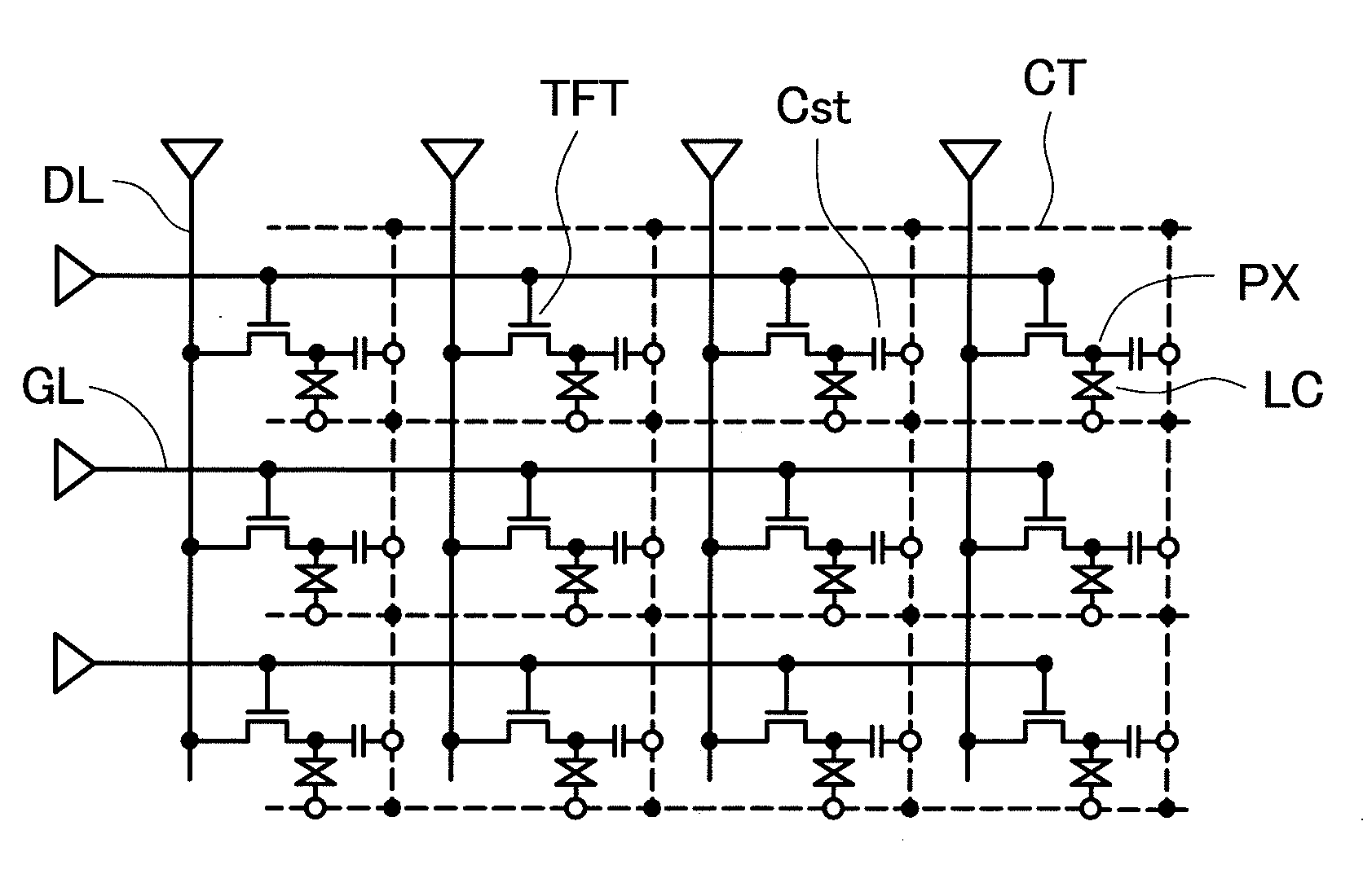
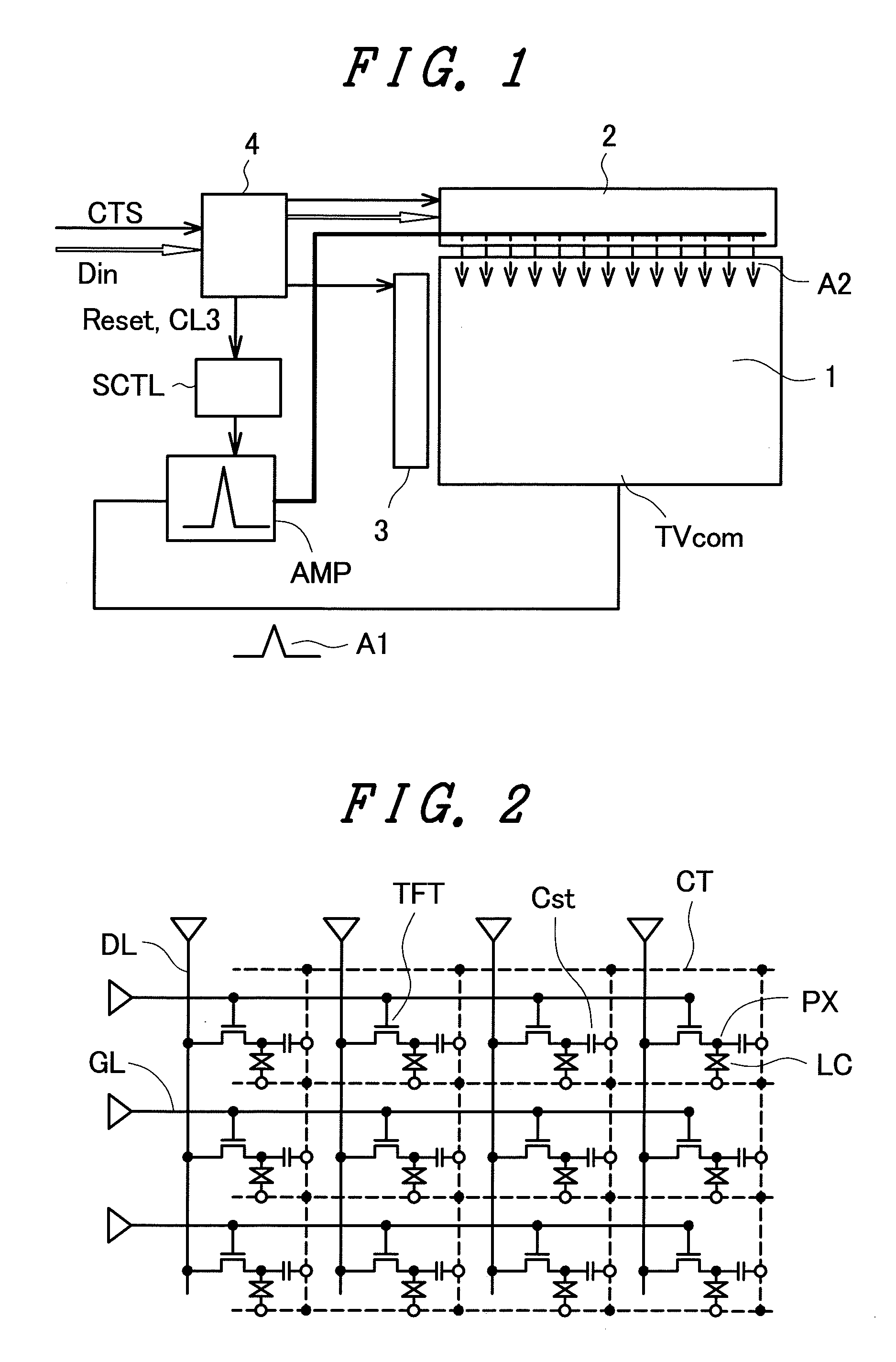
[0039]FIG. 1 shows a schematic configuration of a liquid crystal display module according to an embodiment of the invention. FIG. 2 is a circuit diagram showing an equivalent circuit of a liquid crystal display panel 1 shown in FIG. 1.

[0040]The liquid crystal display module of this embodiment includes the liquid crystal display panel 1, a drain driver 2, a gate driver 3, a display control circuit 4, and a power supply circuit (not shown).

[0041]The liquid crystal display module of this embodiment has a counter voltage detection terminal (TVcom), an inverting amplifier (AMP), and a switching element control circuit (SCTL), as a pixel position-corresponding counter voltage correcting circuit.

[0042]The...


PUM


Abstract

A counter voltage supply circuit has an inverting amplifier that inversely amplified a voltage detected from a specified part of a counter electrode of a liquid crystal display panel and supplies the amplified voltage to a counter voltage supply end of the counter electrode. The inverting amplifier includes an operational amplifier having a feedback resistor connected between an inverting input terminal and an output terminal. The feedback resistor includes a first resistor, and n resistors each of which is connected parallel to the first resistor via a switching element. As the n switching elements are selectively turned on and off by a switching element control circuit in accordance with a scanning position, the resistance value of the feedback resistor is varied and the gain of the operational amplifier is changed. Cross-talk due to coupling noise to the counter electrode generated by AC driving of a video voltage and deterioration in display quantity of a display image on the liquid crystal display panel can be prevented.

Description

[0001]The present application claims priority from Japanese application JP2007-153438 filed on Jun. 11, 2007, the content of which is hereby incorporated by reference into this application.BACKGROUND OF THE INVENTION[0002]1. Field of the Invention[0003]The present invention relates to a liquid crystal display device and particularly to a liquid crystal display device in which a voltage change in a counter electrode of a large-size high-definition liquid crystal display panel is corrected.[0004]2. Description of the Related Art[0005]Recently, liquid crystal display modules have been broadly used for small-size display devices to display devices for OA equipment, large-size television and so on. In the liquid crystal display module, a layer of liquid crystal composite (liquid crystal layer) is held between a pair of insulating substrates, at least one of which is basically made of a transparent glass board, plastic substrate and so on, and a liquid crystal display panel is thus formed...

Claims


Application Information

Patent Timeline
IPC IPC(8): G09G3/36
CPCG09G3/3655G09G2320/0209
Inventor OKE, RYUTAROIMAJO, YOSHIHIRO
Owner PANASONIC LIQUID CRYSTAL DISPLAY CO LTD
Learn More