LCD and Projection Displays

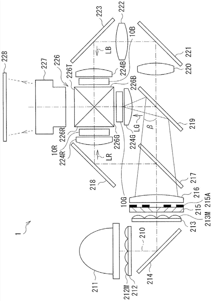
A liquid crystal display and liquid crystal panel technology, which is applied in the direction of using projection device image reproducer, instrument, picture duplicator, etc., can solve the problems of image quality degradation of displayed images, and achieve the purpose of suppressing image quality degradation, reducing reflection, and reducing quantity Effect

Active Publication Date: 2017-11-24
SONY CORP
View PDF1 Cites 0 Cited by
  • Summary
  • Abstract
  • Description
  • Claims
  • Application Information

AI Technical Summary

Problems solved by technology

[0003] Unfortunately, in each of the projection image displays described in Japanese Unexamined Patent Application Publication Nos. 2006-018055 and 2004-045680, the light emitted from the liquid crystal panel is affected by the frame so that the edge portion or the circuit portion is reflected In displaying an image, this disadvantageously degrades the image quality of the displaying image

Method used


Image

  • LCD and Projection Displays
  • LCD and Projection Displays
  • LCD and Projection Displays

Examples


example 2

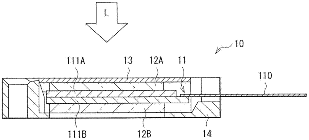
[0071] Figure 17 is an enlarged cross-sectional view illustrating the vicinity of the outer frame 14 according to Modification 2. FIG. As shown in Modification 2, even if the edge portion 14e of the outer frame 14 does not have the above-mentioned slope (S1 or S2) including a plane or a curved surface, and if the height H of the edge portion 14e has a sufficiently small value, for example, 80 μm or less (H=h<80 μm), then effects substantially similar to those in the above-described embodiment can also be obtained.

[0072] Figure 18 The diagram shows the changing Figure 17 Sensory evaluation results of edge reflection in the case of each distance d and height h of the outer frame 14 shown. Evaluations are made on 7 grades, namely, A, A-, B+, B, C+, C, and D+, where grade A represents the highest reflectance level (large image degradation) and grade D+ represents the lowest reflectance level (small image quality degradation). quality deterioration). Generally speaking, ...


PUM

PropertyMeasurementUnit
reflectanceaaaaaaaaaa

Abstract

A liquid crystal display includes: a liquid crystal panel containing an effective pixel region that is configured to emit light corresponding to an image; and a frame member provided on a light emission side of the liquid crystal panel, and having an opening opposed to the effective pixel region of the liquid crystal panel. An edge portion of the opening of the frame member is formed of a low-reflection material having a reflectance of less than about 1.5% to green light.

Description

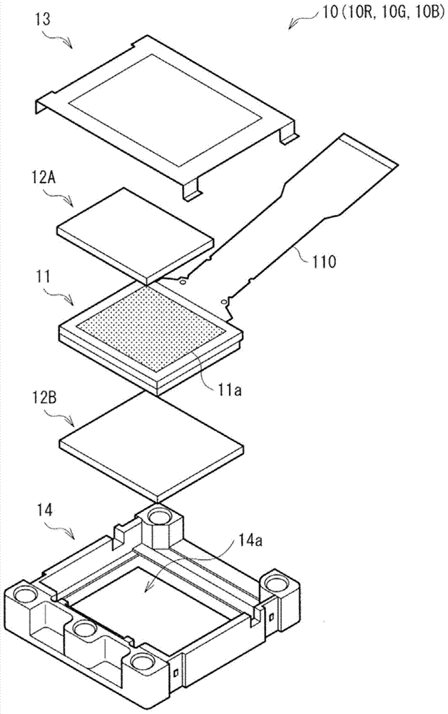
technical field [0001] The present invention relates to liquid crystal displays and projection displays for light valve projectors. Background technique [0002] In a conventional projection display used for a projector or the like, an image is generated based on modulation of light emitted from a light source through a transmissive (or reflective) liquid crystal panel, and the image is displayed in a magnified manner using a projection lens. A frame (outer frame) is attached to the light emitting side of the liquid crystal panel in order to install the liquid crystal panel in the projection display. The outer frame has an opening (window) opposite to the effective pixel area of ​​the liquid crystal panel, and light is extracted to the projection lens side through the opening (for example, see Japanese Unexamined Patent Application Publication Nos. 2006-018055 and 2004-045680). [0003] Unfortunately, in each of the projection image displays described in Japanese Unexamined...

Claims


Application Information

Patent Timeline
Patent Type & Authority Patents(China)
IPC IPC(8): G02F1/13G02F1/1333G02F1/13357G03B21/20G03B21/14H04N9/31
CPCG02F1/133308G03B21/006G02F1/133314H04N9/3152
Inventor 小林宽大村幸一水口义弘平川好宏高木大志
Owner SONY CORP
Why Eureka
Try Eureka