
Method and device for being connected into shortest path bridging network in multi-homing mode

A technology of shortest path bridging and shortest path, which is applied in the field of communication, and can solve problems such as complex realization of multi-homing access shortest path bridging network

Inactive Publication Date: 2014-06-04
ZTE CORP
View PDF6 Cites 2 Cited by
  • Summary
  • Abstract
  • Description
  • Claims
  • Application Information

AI Technical Summary

Problems solved by technology

[0010] The embodiment of the present invention provides a method and device for multi-homing access to the shortest path bridging network, so as to at least solve the technical problem that the method of multi-homing accessing the shortest path bridging network in the prior art is too complicated to implement

Method used


Image

  • Method and device for being connected into shortest path bridging network in multi-homing mode
  • Method and device for being connected into shortest path bridging network in multi-homing mode
  • Method and device for being connected into shortest path bridging network in multi-homing mode

Examples


Embodiment approach 1

[0074] In this preferred embodiment, the local client-side device 1 uses the cross-node link aggregation technology to dual-home to the SPBM network through the network edge node 1 and the network edge node 2, and the remote client-side device 2 uses the cross-node link aggregation technology to dual-home to the SPBM network. technology, dual-homing access to the SPBM network through network edge node 3 and network edge node 4. Assume that all nodes in the network are configured with the same pair (BaseVID, ECT algorithm), where the value of BaseVID is 10, and the value of ECT algorithm is ECT algorithm 1.

[0075] Such as Figure 11 Shown is a schematic diagram of a network scenario of dual-homing at the local end and dual-homing at the remote end in this preferred embodiment 1. The notification and processing process of each network node in this preferred embodiment may include the following steps:

[0076] Step S1: The network edge nodes 1 and 2 including the port of the c...

Embodiment approach 2

[0083] In this preferred embodiment, the local client-side device 1 utilizes the cross-node link aggregation technology to dual-home to the SPBM network through the network edge node 1 and the network edge node 2, and the remote client-side device 2 uses the network edge node 3 to single It is connected to the SPBM network. Assume that all nodes in the network are configured with the same pair (Base VID, ECT algorithm), the value of Base VID is 10, and the value of ECT algorithm is ECT algorithm 1.

[0084] Such as Figure 12 Shown is a schematic diagram of a network scenario of dual-homing at the local end and single-homing at the remote end in this preferred embodiment. The notification and processing process of each network node in this preferred embodiment mainly includes the following steps:

[0085]Step S1: The network edge nodes 1 and 2 including the port of the cross-node LAG (LAG1) notify the B-MAC1 corresponding to LAG1 to the outside, and at the same time notify th...


PUM


Abstract

The invention discloses a method and device for being connected into a shortest path bridging network in a multi-homing mode. The method includes the steps that an LSP message flooded by a border node including a cross-node LAG port in the network is received, wherein the LSP message carries a B-MAC, a Base VID and the portal system serial number of the border node; a B-VID corresponding to the border node is generated according to the Base VID and the portal system serial number; a forwarding table is established according to the B-MAC and the B-VID. By means of the method and device, the technical problem that a method for being connected into the shortest path bridging network in the multi-homing mode in the prior art is complex to implement is solved, and the technical effect for being connected into the shortest path bridging network in the multi-homing mode is achieved under the condition that an existing protocol message is not changed.

Description

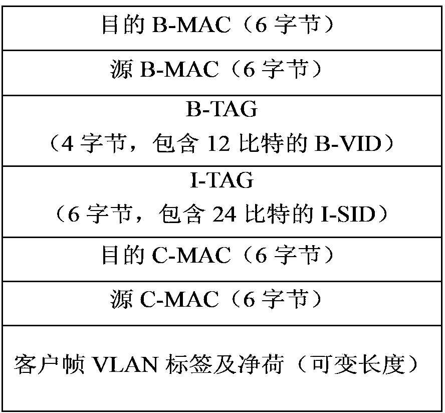
technical field [0001] The present invention relates to the field of communications, in particular to a method and device for multi-homing access to a shortest path bridging network. Background technique [0002] As the application of Ethernet continues to expand from LAN to MAN and backbone network, Ethernet technology is also evolving. The Institute of Electrical and Electronics Engineers (IEEE), an international standard organization, released the 802.1ah Provider Backbone Bridges (Provider Backbone Bridges, PBB) standard and the The 802.1aq Shortest Path Bridging (Shortest Path Bridging, SPB for short) standard, these two standards respectively stipulate the data plane and the control plane of the Ethernet applied to the network backbone layer. [0003] The PBB data plane adopts PBB encapsulation (also known as MAC-in-MAC encapsulation). The specific encapsulation format is as follows: figure 1 As shown in , the Ethernet frame sent by the customer (that is, the custome...

Claims


Application Information

Patent Timeline
IPC IPC(8): H04L12/721H04L47/41H04L45/243
CPCH04L12/465H04L12/4658H04L45/00H04L12/4625H04L12/4633H04L12/4641H04L45/245Y02D30/50H04L41/0803
Inventor 肖敏
Owner ZTE CORP
Learn More