
Centrifugal force pendulum

A technology of centrifugal force pendulum and pendulum quality, which is applied in the field of centrifugal force pendulum, which can solve the problems of limited service life of elastic elements and damage of elastic elements, and achieve the effect of reducing collision noise

Active Publication Date: 2014-06-04
SCHAEFFLER TECH AG & CO KG
View PDF5 Cites 15 Cited by
  • Summary
  • Abstract
  • Description
  • Claims
  • Application Information

AI Technical Summary

Problems solved by technology

The service life of the elastic elements is limited at elevated ambient temperatures
In addition, high-energy impacts can cause damage to elastic elements
The use of additional parts such as spring elements and their fastening elements requires installation space and implies additional costs

Method used


Image

  • Centrifugal force pendulum
  • Centrifugal force pendulum
  • Centrifugal force pendulum

Examples


Embodiment Construction

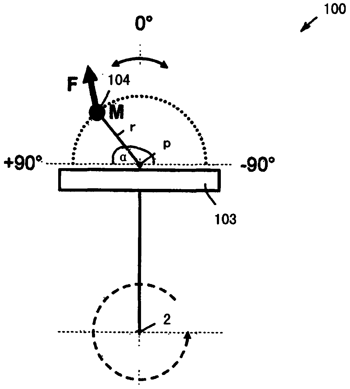
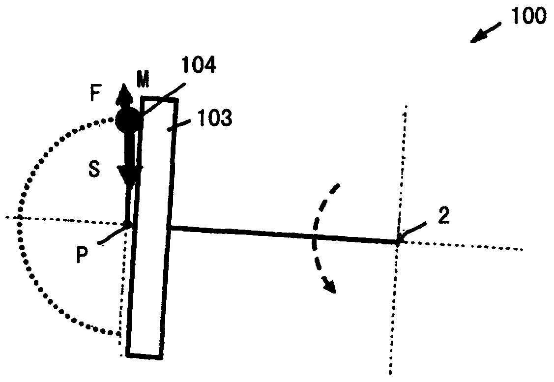
[0025] figure 1 The basic function of a centrifugal pendulum 100 is shown, which has a pendulum flange 103 that rotates about the axis of rotation 2 and a pendulum mass 104 with a center of mass M that is pivotably suspended relative to the pendulum flange on the pivot center point P. . At a constant rotational speed, the center of mass M is accelerated radially outward due to the centrifugal force F and is in an equilibrium position at 0°. If a rotational vibration occurs on the axis of rotation 2, the center of mass M is deflected radially inwards against the centrifugal force F along the vibration angle α, depending on the sign of the moment momentarily transmitted to the pendulum flange 103 and then Again, the excitation frequencies occurring when adjusting the pendulum radius r, the pendulum mass and the oscillation angle α are eliminated in a rotationally adapted manner. Here, the vibration angle α is limited to ±90°. When the maximum oscillation angle is reached, th...


PUM


Abstract

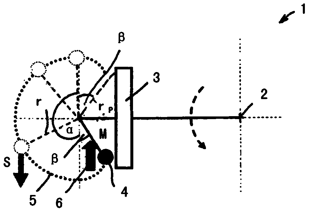
The invention relates to a centrifugal force pendulum (1, 1a) having a pendulum flange (3, 3a) which is arranged so as to be rotatable about an axis of rotation (2) and having a plurality of pendulum masses (4, 4a) which, for rotational-speed-adaptive absorption of rotary oscillations introduced into the pendulum flange (3, 3a), are held so as to be pitovable with a centre of mass (M) about at least one pendulum point (P) with a predefined pendulum radius (r) and a predefined swing angle (a). In order, at low rotational speeds of the pendulum flange (3, 3a), to reduce a generation of noise caused by pendulum masses arranged with the centre of masses thereof above the axis of rotation being accelerated in the direction of the axis of rotation owing to gravitational force, the predefined swing angle (a) is changed by a pendulum angle (ss) with a pendulum radius (rp) which is reduced in relation to the pendulum radius (r).

Description

technical field [0001] The invention relates to a centrifugal pendulum having a pendulum flange arranged torsionably about an axis of rotation and a plurality of pendulum flanges pivotable about at least one center of mass for speed-adaptive damping of rotational vibrations introduced into the pendulum flange The center point of the received pendulum mass oscillates with a predetermined pendulum radius and a predetermined oscillation angle. Background technique [0002] In order to reduce rotational vibrations, such as torsional vibrations of internal combustion engines, for example due to the sequential firing of several cylinders, which have different combustion angles of rotation, only so-called centrifugal pendulums are used or in combination with additional rotational vibration dampers, such as dual-mass flywheels Together with the like, so-called centrifugal pendulums are used, which have a pendulum flange that is generally coaxial with the crankshaft of the internal c...

Claims


Application Information

Patent Timeline
IPC IPC(8): F16F15/14
CPCF16F15/145F16F15/1471
Inventor A·鲁施M·黑斯勒
Owner SCHAEFFLER TECH AG & CO KG
Learn More