Blade arrangement

A technology of blades and damping elements, which is applied in the direction of supporting elements of blades, preventing leakage, and other chemical processes, and can solve problems such as reducing the vibration load of blade devices

Inactive Publication Date: 2013-02-13
SIEMENS AG
View PDF3 Cites 0 Cited by
  • Summary
  • Abstract
  • Description
  • Claims
  • Application Information

AI Technical Summary

Problems solved by technology

This dampens the vibrations and overall leads to a reduction in the vibration load on the blade arrangement

Method used


Image

  • Blade arrangement
  • Blade arrangement

Examples


Embodiment Construction

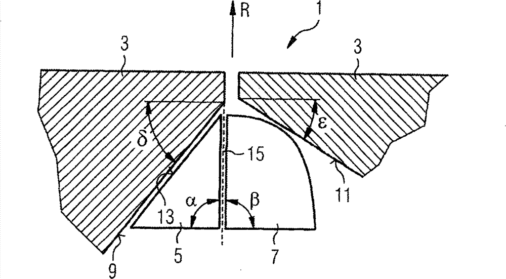
[0016] figure 1 A schematic sectional view of a blade arrangement 1 according to the invention is shown in a section perpendicular to the rotor axis. This sectional view shows two blade platforms 3 of adjacent blades of a blade arrangement 1 according to the invention. The blades are suspended on the rotor disk of the blade arrangement 1 and have a small distance from one another. Two damping elements 5 , 7 are loosely arranged between the two blade platforms 3 . The two damping elements 5 , 7 form a damper group and are axially configured as rods, wherein the damping element 7 has a quarter-circular cross section and the damper 5 has a wedge-shaped cross section.

[0017] The undersides of the two blade platforms 3 form friction surfaces 9 , 11 . The two damping elements 5 , 7 are pressed against said friction surfaces 9 , 11 as a result of centrifugal force when the rotor (not shown) rotates. The friction surfaces 9, 11 now form specific angles δ and ε with the plane for...


PUM


Abstract

A blade arrangement (1) has a rotor and several blades arranged around the periphery of the rotor in a crown. Between two directly adjacent blades at least two damping elements (5,7) are provided and during rotor rotation around an axis, adjacent damping elements make contact between them as caused by the centrifugal force acting in a radial direction, and one of the damping elements makes contact with one of the two blades and the other of the two damping elements (7,5) makes contact with the other blade. Two of the contacts are flat and one of the contacts is linear.

Description

technical field [0001] The invention relates to a blade arrangement having a rotor and a plurality of blades arranged on a rim along the circumference of the rotor, wherein at least two damping elements are arranged one behind the other along the circumference of the rotor at two directly adjacent between the blades, and wherein, due to the centrifugal force acting in the radial direction, when the rotor rotates around the rotor axis, adjacent damping elements contact each other, and one of the two damping elements is in contact with the two of the blades One is in contact and the other damping element is in contact with the other of the two said vanes. Background technique [0002] It is known that blade arrangements used in turbomachines, such as gas turbines, are equipped with damping elements. The damping element serves to damp undesired bending and torsional vibrations that occur during turbine operation due to different excitations. In this way, HCF damage due to hig...

Claims


Application Information

Patent Timeline
Patent Type & Authority Patents(China)
IPC IPC(8): F01D5/22F01D11/00
CPCY10S416/50F01D11/008F01D5/22F05D2250/23F05D2250/231F05B2250/23F05B2250/231
Inventor 安德烈亚斯·凯泽
Owner SIEMENS AG
Why Eureka
Try Eureka