Vehicle Vibration Reduction Device
A power transmission device, vehicle technology, applied in the direction of vibration suppression adjustment, hybrid vehicles, gear vibration/noise attenuation, etc., to achieve the effect of reducing vibration
- Summary
- Abstract
- Description
- Claims
- Application Information
AI Technical Summary
Problems solved by technology
Method used
Image


Examples
Embodiment approach 1
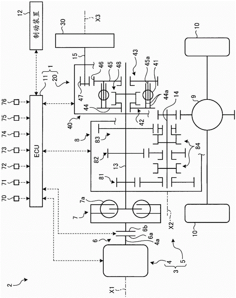
[0025] figure 1 is a schematic configuration diagram of the vehicle vibration reducing device according to Embodiment 1, figure 2 It is a diagram illustrating an example of the operation of the vehicle vibration reducing device according to the first embodiment.
[0026] In the following description, unless otherwise specified, the directions along the rotation axes X1, X2, and X3 are referred to as axial directions, respectively, and the directions perpendicular to the rotation axes X1, X2, and X3, that is, the axial directions The directions perpendicular to each other are called radial directions, and the directions around the rotation axes X1, X2, and X3 are called circumferential directions, respectively. In addition, in the radial direction, the rotation axis X1, X2, X3 side is referred to as the radially inner side, and the opposite side is referred to as the radially outer side.
[0027] Such as figure 1 As shown, the vehicle vibration reducing device 1 of the pres...
Embodiment approach 2
[0073] image 3 It is a schematic configuration diagram of a vehicle vibration reducing device according to Embodiment 2. The vehicle vibration reducing device according to Embodiment 2 differs from Embodiment 1 in the configuration of the switching device. In addition, overlapping descriptions of configurations, functions, and effects common to those of the above-mentioned embodiments will be omitted as much as possible (the same applies to the embodiments described later).
[0074] image 3 The shown vehicle vibration reducing device 201 according to the present embodiment includes a vibration reducing device main body 220 and an ECU 11 as a control device that controls the vibration reducing device main body 220 . The vibration reducing device main body 220 has the reducing device rotating shaft 15 , the rotating body 30 , and the switching device 240 . The switching device 240 can switch between the first path 42 and the second path 43 .
[0075] The switching device 2...
Embodiment approach 3
[0085] Figure 4 is a schematic configuration diagram of a vehicle vibration reducing device according to Embodiment 3, Figure 5 It is a diagram illustrating an example of the operation of the vehicle vibration reducing device according to the third embodiment. The vehicle vibration reducing device according to Embodiment 3 is different from Embodiments 1 and 2 in the configuration of the switching device.
[0086] Figure 4 The shown vehicle vibration reducing device 301 according to the present embodiment includes a vibration reducing device main body 320 and an ECU 11 as a control device that controls the vibration reducing device main body 320 . The vibration reducing device main body 320 has the reducing device rotating shaft 15 , the rotating body 30 , and the switching device 340 . The switching device 340 can switch between the first path 42 and the second path 43 .
[0087]The switching device 340 of this embodiment is configured to include a spring 41, a first d...
PUM
 Abstract
Description
Claims
Application Information
 - R&D
- Intellectual Property
- Life Sciences
- Materials
- Tech Scout
- Unparalleled Data Quality
- Higher Quality Content
- 60% Fewer Hallucinations
Browse by: Latest US Patents, China's latest patents, Technical Efficacy Thesaurus, Application Domain, Technology Topic, Popular Technical Reports.
© 2025 PatSnap. All rights reserved.Legal|Privacy policy|Modern Slavery Act Transparency Statement|Sitemap|About US| Contact US: help@patsnap.com