Carrier-suppressed light-generating device

A generation device, carrier suppression technology, applied in optics, nonlinear optics, electromagnetic wave transmission systems, etc., can solve problems such as extinction ratio dependence

Active Publication Date: 2014-06-04
SUMITOMO OSAKA CEMENT CO LTD
View PDF3 Cites 10 Cited by
  • Summary
  • Abstract
  • Description
  • Claims
  • Application Information

AI Technical Summary

Problems solved by technology

However, in this method, the loss due to defects is wavelength-dependent, and the extinction ratio is also wavelength-dependent, which poses a problem

Method used


Image

  • Carrier-suppressed light-generating device
  • Carrier-suppressed light-generating device
  • Carrier-suppressed light-generating device

Examples


no. 1 Embodiment approach

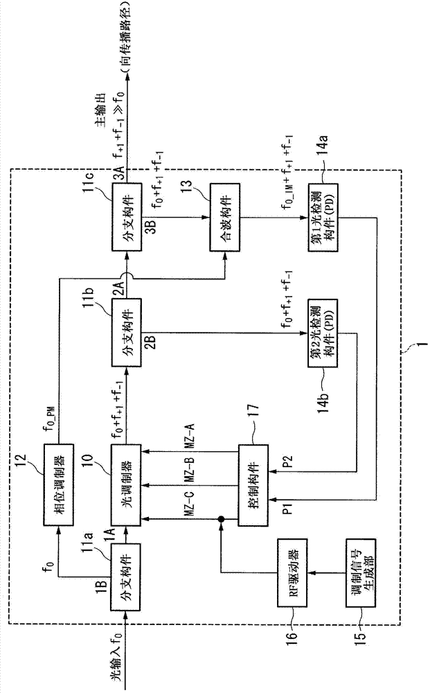
[0039] figure 1 It is a figure which shows the structure of the carrier suppression light generation apparatus 1 which concerns on one Embodiment of this invention.

[0040] In this figure, as the frequency f of the input light to the carrier-suppressed optical generator 1 0 The light (carrier light) is branched into two beams 1A and 1B by the branching member 11 a , one beam 1A is input to the optical modulator 10 , and the other beam 1B is input to the phase modulator 12 .

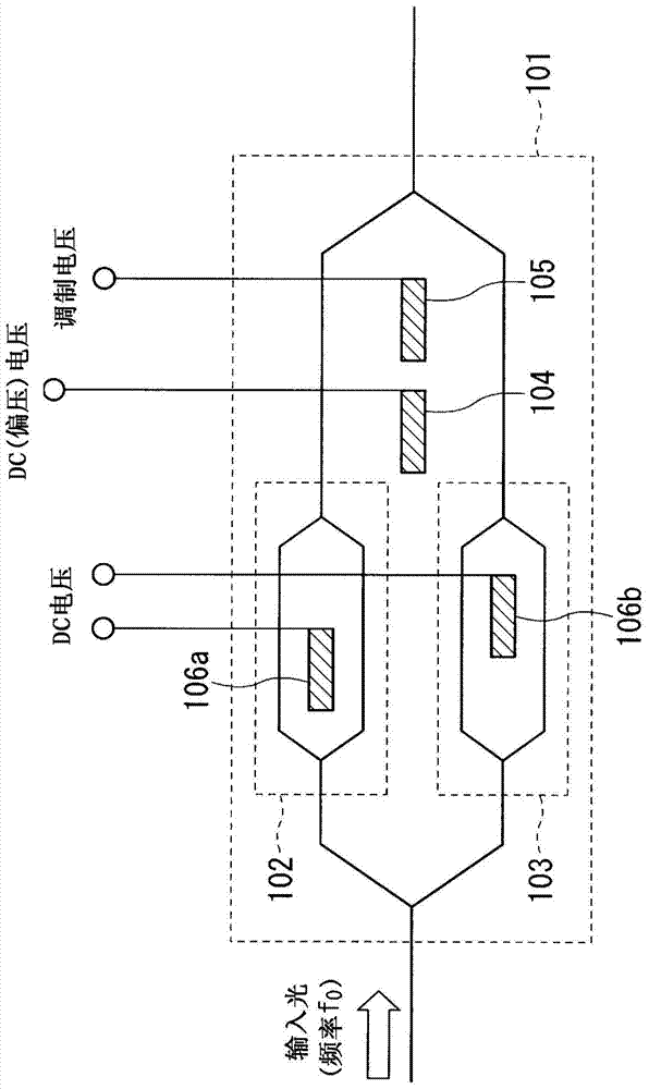
[0041] According to the frequency f generated by the modulation signal generator 15, the optical modulator 10 m modulation signal to modulate the input light 1A. Thus, the output carrier light f is removed from the optical modulator 10 0 In addition, the output includes a different frequency f from the carrier light +1 and f -1 The edge of the light is light. Among them, f +1 = f 0 + f m , f -1 = f 0 -f m . Also, with frequency f m When modulated, a higher order component f also occurs 0 ±...

no. 2 Embodiment approach

[0066] Figure 4 It is a figure which shows the structure of the carrier suppression light generation apparatus 1 which concerns on the 2nd Embodiment of this invention.

[0067] In this figure, the input light to the carrier suppression optical generator 1 is the frequency f 0 The light (carrier light) is branched into two beams 1A and 1B by the branching member 11 a , one beam 1A is input to the optical modulator 10 , and the other beam 1B is input to the phase modulator 12 .

[0068] According to the frequency f generated by the modulation signal generator 15, the optical modulator 10 m modulation signal to modulate the input light 1A. As the optical modulator 10, the same device as that of the first embodiment can be used.

[0069] The output light from the optical modulator 10 is branched into two beams 2A and 2B by the branching member 11c, one beam 2A is output to the propagation path as the main output of the carrier suppressing light generating device 1, and the ot...

no. 3 Embodiment approach

[0085] Figure 5 It is a figure which shows the structure of the carrier suppression light generation apparatus 1 which concerns on the 3rd Embodiment of this invention.

[0086] In this embodiment, instead of the multiplexer 13 in the configuration of the second embodiment, a multiplexer / demultiplexer 13A that outputs two output lights at a constant branching ratio after multiplexing two input lights is used, and the two The beam output light is received by a differential detection means 19 such as a differential PD.

[0087] The configuration until the input light to the carrier suppressing optical generator 1 is input to the multiplexer / demultiplexer 13 a is the same as that of the second embodiment, and thus description thereof will be omitted.

[0088] The first input light 2B and the second input light respectively input to the multiplexing / demultiplexing component 13a from the branching component 11c and the phase modulator 12 are multiplexed and interfered by the mult...


PUM


Abstract

The present invention makes it possible to suppress carrier light with a simple configuration in the process of modulating carrier light and generating sideband light. This carrier-suppressed light-generating device comprises: a first splitting means for splitting inputted carrier light into two; an optical modulator for modulating one of the split carrier lights and outputting light that includes sideband light; a phase modulator for phase-modulating the other of the split carrier lights; and a second or third splitting means for splitting the output light of the optical modulator into two. The output light split by the second or third splitting means and the output light of the phase modulator are converged, whereby the amplitude of the time waveform of the optical power is found and the optical modulator is controlled so that the value thereof reaches a minimum.

Description

technical field [0001] The present invention relates to a technique for suppressing carrier light when the carrier light is modulated to generate sideband light. [0002] this application claims priority based on Japanese Patent Application No. 2011-217794 for which it applied to Japan on September 30, 2011, The content is used here. Background technique [0003] In an optical communication system in which signals are carried on light and propagated through optical fibers, an optical intensity modulator that modulates the intensity of laser light emitted from a light source to generate an optical signal is used. Light intensity modulators in, for example, lithium niobate (LiNbO 3 , hereinafter abbreviated as LN) and other electro-optical crystal substrates are formed with Mach-Zehnder type optical waveguides, modulation electrodes and bias electrodes. [0004] The Mach-Zehnder type optical waveguide has a waveguide structure composed of: a branch part that branches the inp...

Claims


Application Information

Patent Timeline
Patent Type & Authority Applications(China)
IPC IPC(8): G02F1/035H04B10/516
CPCH04B10/5165H04B10/5053H04B10/5057H04B10/548H04B10/564
Inventor 坂井猛牟礼胜仁市川润一郎
Owner SUMITOMO OSAKA CEMENT CO LTD
Why Eureka
Try Eureka