
Driving device for forming machine

A driving device and forming machine technology, applied in packaging, packaging machines, transportation and packaging, etc., can solve problems such as stuck, shortened replacement cycle, and reduced work efficiency, and achieve a simple overall structure, long service life, and ingenious design Effect

Inactive Publication Date: 2014-06-11
陈建群
View PDF0 Cites 0 Cited by
  • Summary
  • Abstract
  • Description
  • Claims
  • Application Information

AI Technical Summary

Problems solved by technology

At present, although the telescopic mechanisms on the existing molding machines can roughly meet the requirements of use, their designs are not ingenious enough, and none of them can break through the traditional structural design. They all use spring-type telescopic mechanisms. The following problems arise: 1. During the compression process of the spring, as the rigidity of the pitch increases and the elastic force increases, the casing of the lower die bears a large load, which reduces the service life of the casing and shortens the replacement cycle
2. The spring is prone to fatigue and damage under the action of repeated alternating carrier, which affects the normal operation of the machine
3. Due to the effect of the eccentric carrier of the spring, the up and down telescopic movement of the lower mold casing is often inflexible, or even stuck, which seriously affects the completion of the packaging process, greatly reduces work efficiency, and is difficult to guarantee product quality, which is not conducive to enterprise development

Method used


Image

  • Driving device for forming machine

Examples


Embodiment Construction

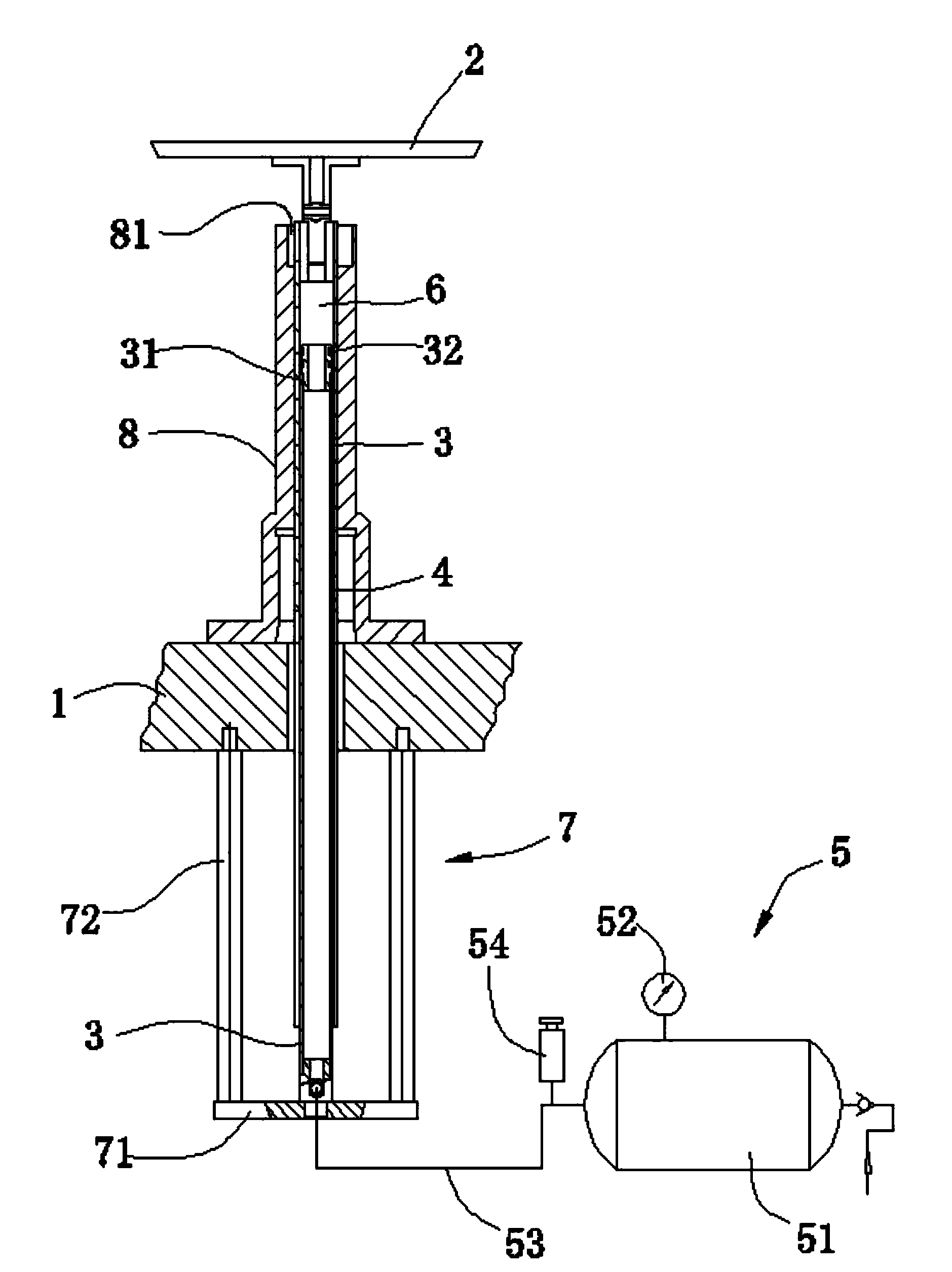
[0014] See figure 1 This embodiment provides a molding machine driving device, which includes a base 1 and a lower mold base plate 2, which also includes a lower mold inner sleeve 3, a lower mold outer sleeve 4, and an air supply device 5. The in-mold sleeve 3 is fixed on the support 1, the lower mold base plate 2 is fixed on the top of the lower mold outer sleeve 4, and the bottom of the lower mold outer sleeve 4 is movably sleeved on the lower mold On the inner sleeve 3, a closed space 6 is formed between the inner sleeve 3 of the lower mold and the inner hole of the outer sleeve 4 of the lower mold, and the air supply device 5 communicates with the closed space 6.

[0015] The lower end of the lower mold inner sleeve 3 penetrates the support 1, and corresponding to the bottom of the support 1 is provided with a fixing frame 7 for fixing the lower mold inner sleeve 3 on the support 1 .

[0016] The fixing frame 7 includes a connecting plate 71 and two fixing posts 72. The lower...


PUM


Abstract

The invention discloses a driving device for a forming machine. The driving device comprises a support, a lower die substrate, a lower die inner sleeve, a lower die outer sleeve and an air supply unit. The lower end of the lower die inner sleeve penetrates the support, and a fixing frame for fixing the lower die inner sleeve on the support is arranged at the bottom of the support correspondingly. According to the driving device, the design is ingenious, when the a lower die outer sleeve presses down, air in sealed space is compressed automatically, and a spring function is provided; the air pressure of the sealed space can be controlled skillfully by the air supply unit according to the work condition of the lower die substrate to obtain corresponding elastic force, so that the driving device is flexible in stretching and retraction and high in stability.

Description

Technical field [0001] The present invention relates to the technical field of molding machines, in particular to a driving device of a molding machine. Background technique [0002] With the development of science and technology, modern people pay more and more attention to the improvement and perfection of molding machines. Therefore, there are various molding machines on the market, each with a different design concept, and strive to meet the requirements of different users. At present, although the telescopic mechanism on the existing molding machine can roughly meet the requirements of use, its design is not clever enough, and they have failed to break through the traditional structural design. All of them use spring-type telescopic mechanisms, and the lower mold telescopes to complete the packaging process. The following problems occur: 1. As the rigidity of the pitch increases and the elastic force increases during the compression of the spring, the lower die casing bears...

Claims


Application Information

Patent Timeline
Patent Type & Authority Applications(China)
IPC IPC(8): B65B65/00
Inventor 陈建群
Owner 陈建群
Learn More