Slope friction vibration isolation system

A technology of seismic isolation system and inclined plane, which is applied in the direction of earthquake resistance and building components, can solve the problems of frictional sliding pendulum bearing damage, danger of upper device, difficulty in structural reset, etc., and achieve easy construction and manufacturing, easy reset, and reduce overturning damage risk effect

Active Publication Date: 2014-06-11
熊伟
View PDF4 Cites 4 Cited by
  • Summary
  • Abstract
  • Description
  • Claims
  • Application Information

AI Technical Summary

Problems solved by technology

However, due to the particularity of the structure of the friction-sliding pendulum bearing in FPS and TFPS, on the one hand, it is difficult to reset the structure under the action of a large pulse earthquake, and the seismic-isolation bearing will produce a certain residual displacement compared with its original state, which becomes Obstacles in engineering applications; on the other hand, due to the excessive vertical response of the near-field earthquake, the severe earthquake force is easy to "throw away" the sliding block in the support from the concave sliding surface of the upper device, resulting in the entire frictional sliding The support breaks, putting the topside in danger
Moreover, when the displacement is too large, the central sliders of FPS and TFPS may collide with the surrounding wall of the sliding concave edge, so that the vibration isolation bearing is in danger of being damaged

Method used


Image

  • Slope friction vibration isolation system
  • Slope friction vibration isolation system
  • Slope friction vibration isolation system

Examples


Embodiment Construction

[0018] The present invention will be described in further detail below in conjunction with the accompanying drawings and embodiments.

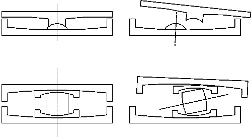
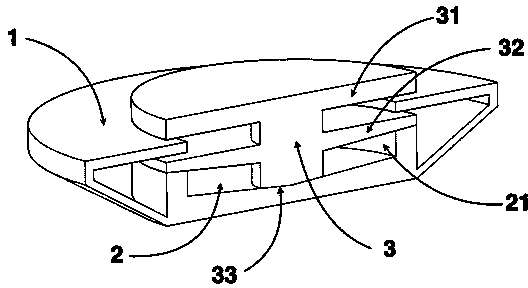
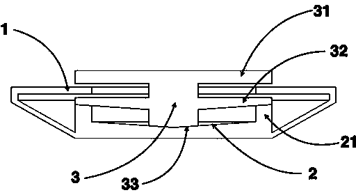
[0019] refer to figure 1 and figure 2 , the slope friction shock isolation system provided in this embodiment includes a baffle 1 , a conical sliding concave surface 2 and a central column 3 that can move between the baffle 1 and the conical sliding concave surface 2 .

[0020] The central column 3 is composed of an upper flange 31 , a lower flange 32 and a conical sliding convex surface 33 . The central column 3 is divided into two layers by the upper flange 31 and the lower flange 32. Its central section is arranged in the shape of "dry" and is combined with the conical sliding convex surface 33. When the vertical vibration of the near-field earthquake is too large and the conical When the conical sliding convex surface 33 is lifted off, the phenomenon that the conical sliding convex surface 33 is thrown out can be reduced, which effectiv...


PUM


Abstract

The invention relates to a slope friction vibration isolation system, which comprises a retaining plate, a conical sliding concave surface and a center column, wherein the center column can move between the retaining plate and the conical sliding concave surface, and consists of an upper flange, a lower flange and a conical sliding convex surface, the titling angle of the conical sliding convex surface is in engaged contact with the tilting angle of the center of the conical sliding concave surface, the edge of the conical sliding concave surface vertically extends out of a surrounding wall, the upper end of the surrounding wall is in contact with the lower surface of the lower flange, the upper end surface of the retaining plate is embedded between the upper flange and the lower flange, and the lower end of the retaining plate is connected with the conical sliding concave surface. The system has the advantages that the resetting of the structure is easily implemented during the near-field large pulse earthquake, the vertical disengagement of the center column is effectively prevented, the risk of overturning damage of the vibration isolation system is reduced, and the damage danger of the center column and the surrounding wall caused by overlarge horizontal displacement is avoided; the wide popularization and application value is realized in the fields of earthquake engineering, structure engineering and other civil engineering.

Description

technical field [0001] The invention relates to a shock-isolation system in earthquake engineering, structural engineering and other civil engineering, in particular to an inclined plane friction shock-isolation system. Background technique [0002] Seismic isolation structure is a form of passive shock-absorbing structure that protects the upper structure by isolating earthquake vibrations through the seismic-isolation layer. The seismic isolation structure mainly reduces the seismic energy entering the superstructure by prolonging the basic period of the structure, and reduces the seismic response of the structure to achieve the purpose of earthquake isolation. In seismically isolated buildings, the proportion of passive foundation isolation is relatively large. The so-called base isolation refers to decoupling from the foundation by installing a horizontally flexible seismic isolation system between the superstructure and the foundation. The more developed and researche...

Claims


Application Information

Patent Timeline
IPC IPC(8): E04B1/98
Inventor 熊伟
Owner 熊伟
Why Eureka
Try Eureka