Carrier element for pressure chamber of friction clutch

A friction clutch and bearing element technology, applied in clutches, fluid-driven clutches, non-mechanical-driven clutches, etc., can solve the problems of labor-intensive manufacturing, complex and expensive structure of friction clutches, etc. Effect

Active Publication Date: 2014-06-11
SCHAEFFLER TECH AG & CO KG
View PDF5 Cites 4 Cited by
  • Summary
  • Abstract
  • Description
  • Claims
  • Application Information

AI Technical Summary

Problems solved by technology

Therefore, such a friction clutch construction is very complicated
The production of such a friction

Method used


Image

  • Carrier element for pressure chamber of friction clutch
  • Carrier element for pressure chamber of friction clutch
  • Carrier element for pressure chamber of friction clutch

Examples


Embodiment Construction

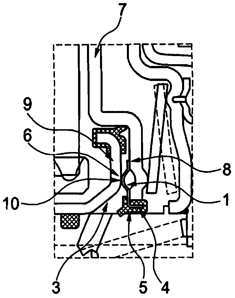
[0037] figure 1 Shown is a carrier element 1 which is arranged in a pressure chamber 3 of a friction clutch 2 (not shown here). The carrier element 1 has a stop element 6 which is embodied as a projection 10 and has a further stop 8 . The actuating element 7 of the friction clutch 2 is arranged in the smallest stop position in the pressure chamber 3 , so that the projection 10 of the stop element 6 bears against the part 9 , here the wall of the pressure chamber . The receiving element 4 has a sealing means 5 which is designed here as an axial slide element and seals off the pressure chamber 3 in an axially movable manner. The carrier element 1 is connected to the actuating element 7 via the receiving element 4 or indirectly via the sealing means 5 .

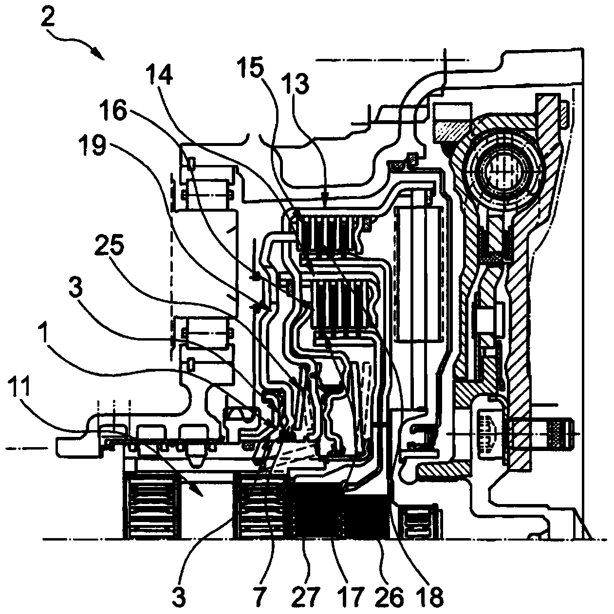
[0038] exist figure 2 The friction clutch 2 is shown in , which includes a first friction set 13 and a second friction set 14 , the friction sets include at least one first pressure plate 15 and a second pressure plate 16 res...


PUM


Abstract

The present invention relates to a carrier element for a pressure chamber of a friction clutch. The carrier element is provided with at least a receiving element for a sealing device and a stopping element for an operation element of a pressure chamber. The carrier element is characterized by employing an integral structure. By employing the carrier element, a plurality of elements can be replaced by the carrier element which is very light in weight and simple in structure.

Description

technical field [0001] The invention relates to a carrier element for a pressure chamber of a friction clutch, in particular a motor vehicle friction clutch. Background technique [0002] Various hydraulically actuated friction clutches are known from the prior art. For this purpose, a piston movable back and forth by means of a pressure chamber is provided in the friction clutch. The piston is normally moved in the engagement direction by means of the fluid pressure in the pressure chamber. When the fluid pressure in the pressure chamber decreases, the piston is moved back in the direction of separation by means of an elastic element. In this case, the direction indication is not necessarily the same as the engagement and disengagement of the friction elements of the friction clutch, but usually the opposite. For the return movement, an end stop is provided which limits the minimum position of the reciprocating movement of the piston. In efficient friction clutches, a g...

Claims


Application Information

Patent Timeline
IPC IPC(8): F16D25/12
CPCF16D25/12F16D25/0638F16D2300/08
Inventor A·阿尔默特J·阿诺尔德A·鲍姆加特纳
Owner SCHAEFFLER TECH AG & CO KG
Why Eureka
Try Eureka