Display method and electronic equipment

A technology of electronic equipment and display method, applied in the field of electronics, can solve the problem of inability to adjust the display direction of the screen, and achieve the effect of enhancing 3D effect, enhancing realism, and improving physical comfort.

Active Publication Date: 2014-06-11
LENOVO (BEIJING) CO LTD
View PDF3 Cites 4 Cited by
  • Summary
  • Abstract
  • Description
  • Claims
  • Application Information

AI Technical Summary

Problems solved by technology

[0006] The present invention provides a display method and an electronic device to solve the technical problem in the prior

Method used


Image

  • Display method and electronic equipment
  • Display method and electronic equipment
  • Display method and electronic equipment

Examples


Example Embodiment

[0065] Example one:

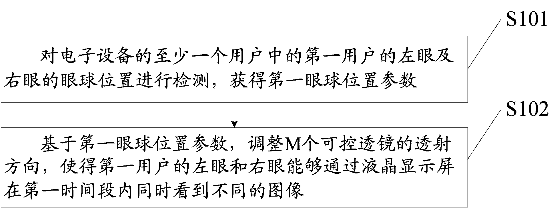
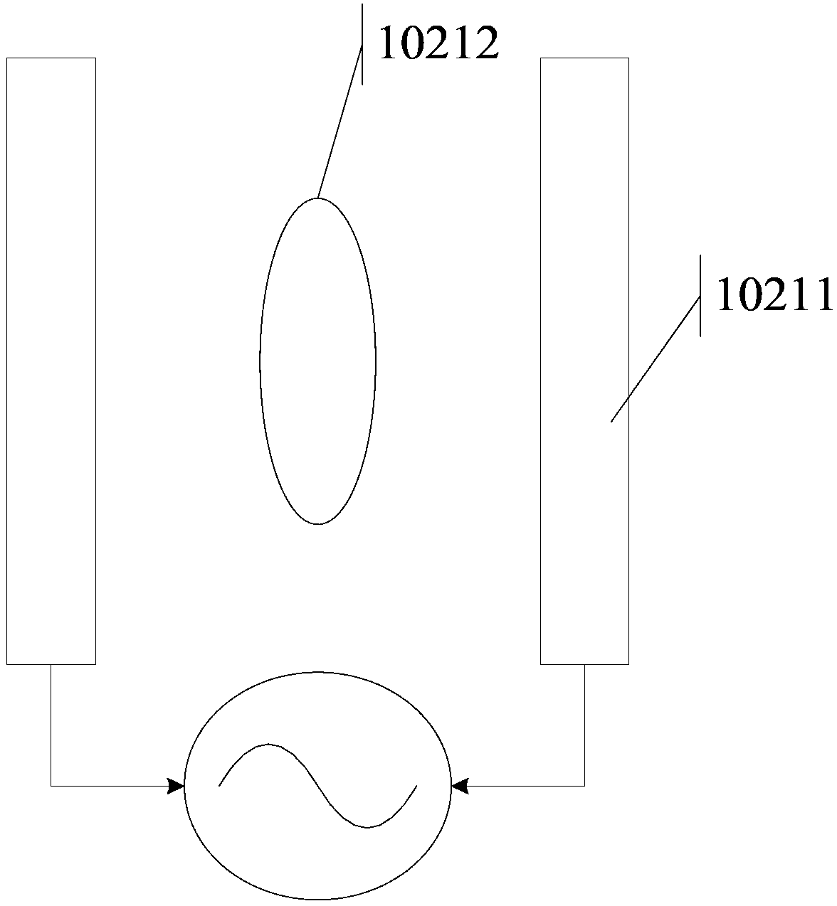
[0066] The electronic device is a tablet computer. Assuming that the first user is watching a 3D movie on a tablet computer, first, the front camera set on the tablet computer will track the eyes of the first user to obtain the first eye position parameter, that is, the left eye of the first user Position, and the position of the first user’s right eye. Then, according to the first eyeball position parameter, the gaze direction of the left eye and the right eye is judged. At this time, as Figure 4 As shown, the angle (acute angle) between the line of sight of the left eye and the surface of the LCD screen of the tablet computer is 45°, and the angle (acute angle) between the line of sight of the right eye and the surface of the LCD screen of the tablet computer is 45°. Next, the tablet computer will adjust the charge distribution on the transparent electrode plate 10211 according to the first eyeball position parameter, so that the electric field intensity...

Example Embodiment

[0067] Embodiment two:

[0068] The electronic device is a handheld game console. When the first user is using a handheld game console to play a 3D game, first, the front camera set on the handheld game console will track the eyes of the first user to obtain the first eyeball position parameter, that is, the first user’s The position of the left eye and the position of the right eye of the first user. Then, according to the first eyeball position parameter, the gaze directions of the left eye and the right eye are determined. Such as Figure 4 As shown, at this time, at the first time T1, the angle (acute angle) between the line of sight of the left eye and the surface of the LCD screen of the game machine is 45°, and the line of sight of the right eye is clamped to the surface of the LCD screen of the tablet computer. The angle (acute angle) is 45°. Next, the game machine will adjust the charge distribution on the transparent plate 10211 according to the direction of the left...

Example Embodiment

[0069] Example three:

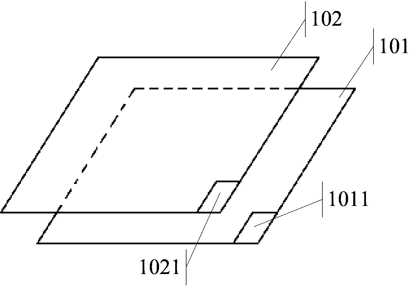
[0070] The electronic device is a smart TV, and there is a polarization layer 103 between the liquid crystal display layer 101 and the controllable lens layer 102. When the first user uses a smart TV to play a 3D game, first, the smart TV will display an interactive interface, allowing the first user to set which eye the polarizers with different polarization directions correspond to. For example, the first polarizer whose polarization direction is set by the first user as the horizontal direction corresponds to the user's left eye, and the second polarizer whose polarization direction is the vertical direction corresponds to the user's right eye. Then, the front camera set on the smart TV will perform eye tracking on the eyes of the first user to obtain the first eye position parameter, that is, the left eye position of the first user and the right eye position of the first user . Next, according to the first eyeball position parameter, determine the di...


PUM


Abstract

The invention discloses a display method and electronic equipment. The method is applied to the electronic equipment which comprises a liquid crystal display (LCD) screen, wherein the LCD screen comprises an LCD layer consisting of M pixels, and a controllable lens layer consisting of M controllable lenses; the controllable lens layer is arranged above the LCD layer; the M controllable lenses and the M pixels are in one-to-one correspondence, wherein M is an integer greater than or equal to 1. The method comprises the steps of testing the eyeball positions of the left and right eyes of the first user in at least one user of the electronic equipment so as to obtain the first eyeball position parameter; adjusting the transmission directions of the M controllable lenses based on the first eyeball position parameter, so that through the adoption of the first user's left and right eyes, different images at the same time within the first period of time can be seen through the LCD screen.

Description

technical field [0001] The invention relates to the field of electronic technology, in particular to a display method and electronic equipment. Background technique [0002] With the development of science and technology, 3D technology is becoming more and more mature. In order to meet the needs of users, glasses-free 3D technology is widely used in various electronic devices, such as notebook computers, smart TVs, tablet computers, game consoles, etc. [0003] At present, 3D imaging is produced by the visual difference between two eyes. There is generally a distance of about 8 cm between the eyes (pupils) of a person. To make people see 3D images, it is necessary to allow the left eye and right eye to see different images, so that there is a certain gap between the two images, that is, to simulate the actual viewing situation of human eyes, so that the two images can be combined by the brain Combining an image, the 3D stereoscopic feeling comes from this. Now, users who ...

Claims


Application Information

Patent Timeline
IPC IPC(8): G02F1/1335G02B27/26H04N13/04G02B30/25
Inventor 阳光尚可张振华
Owner LENOVO (BEIJING) CO LTD
Why Eureka
Try Eureka