Method for realizing synchronous PTP motion in robots and device thereof

A robot and motion time technology, applied in the field of robotics, can solve problems such as the inability to complete trajectory point generation

Active Publication Date: 2014-06-11
PEITIAN ROBOTICS CO LTD
View PDF8 Cites 26 Cited by
  • Summary
  • Abstract
  • Description
  • Claims
  • Application Information

AI Technical Summary

Problems solved by technology

In the real-time planning process of robot control, the above method may lead to the i

Method used


Image

  • Method for realizing synchronous PTP motion in robots and device thereof
  • Method for realizing synchronous PTP motion in robots and device thereof
  • Method for realizing synchronous PTP motion in robots and device thereof

Examples


Embodiment Construction

[0037] The present invention will be described in detail below in conjunction with the accompanying drawings and embodiments.

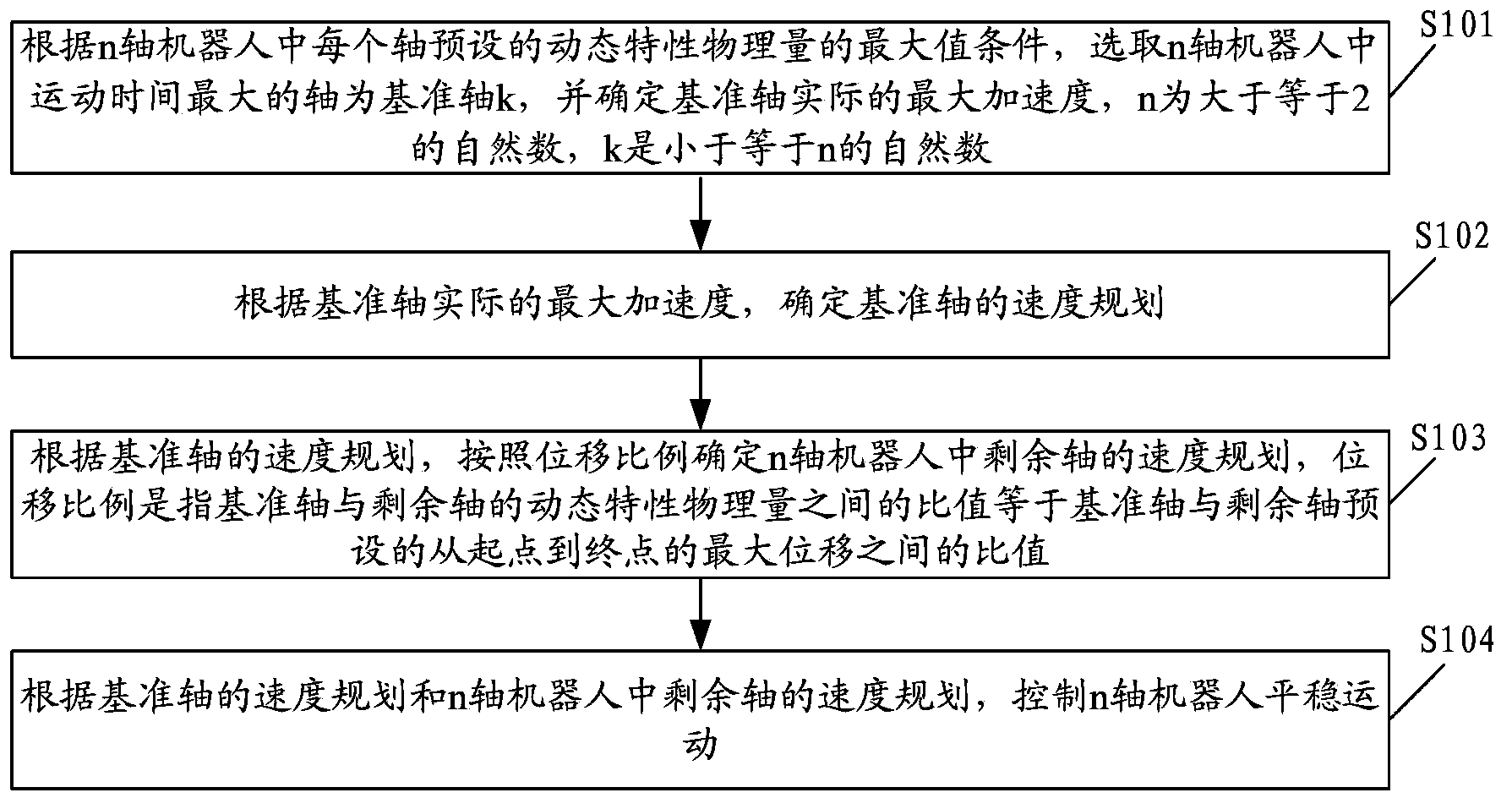
[0038] refer to figure 1 , figure 1 It is a flowchart of an embodiment of a method for realizing synchronous point-to-point PTP motion in the robot of the present invention, including:

[0039] Step S101: According to the maximum condition of the preset dynamic characteristic physical quantity of each axis in the n-axis robot, select the axis with the largest movement time in the n-axis robot as the reference axis k, and determine the actual maximum acceleration of the reference axis, n is greater than or equal to is a natural number of 2, and k is a natural number less than or equal to n.

[0040] A robot is a machine device that performs work automatically, and is a machine that realizes various functions by its own power and control capabilities. According to ISO 8373, a robot is defined as an industrial automation device whose position can be f...


PUM


Abstract

The invention discloses a method for realizing synchronous PTP motion in robots and a device thereof. The method comprises the following steps: an axis with the longest run duration in the n-axis robot is selected as the reference axis according to maximum condition of preset dynamic characteristic physical quantities of each axis in a robot; the actual maximum acceleration of the reference axis is determined; velocity planning of the reference axis is determined according to the actual maximum acceleration of the reference axis; and velocity planning of residual axis in the robot is determined according to displacement ratio. By the above mode, synchronous PTP planning can be completed with the smallest calculated quantity, and strict consistency of run duration of each axis in the robot is guaranteed.

Description

technical field [0001] The invention relates to the technical field of robots, in particular to a method and device for realizing PTP motion in a robot. Background technique [0002] In industrial robot control, point-to-point (PTP, Point to Point) motion generally requires synchronous PTP motion, that is, all axes of the robot start and stop at the same time. Compared with asynchronous PTP motion, the time it takes for the robot to reach the target point in synchronous PTP motion is the same as the time it takes to reach the target point in asynchronous PTP motion; however, in synchronous PTP motion, the movement speed of each axis of the robot and Acceleration can be smaller. Therefore, compared with asynchronous PTP motion, the synchronous PTP movement has a smaller load on each axis of the robot, less impact on the machine, and is also safer. [0003] In order to realize the synchronous PTP motion, the method in the prior art is to carry out trajectory planning for the...

Claims


Application Information

Patent Timeline
IPC IPC(8): G05B13/04
Inventor 叶根
Owner PEITIAN ROBOTICS CO LTD
Why Eureka
Try Eureka