Method for reducing downlink control channel disturbance

A control channel and power reduction technology, which is applied in the field of reducing downlink control channel interference, can solve the problems of heavy PDCCH load, heavy PDCCH load received on service channels, and is not suitable for homogeneous macro base station networking scenarios, so as to avoid PDCCH overload. Reducing the effect of PDCCH channel interference

Inactive Publication Date: 2014-06-11
POTEVIO INFORMATION TECH
View PDF3 Cites 5 Cited by
  • Summary
  • Abstract
  • Description
  • Claims
  • Application Information

AI Technical Summary

Problems solved by technology

[0006] The above solution uses cross-carrier scheduling to effectively avoid the interference between the downlink control channels of the macro base station and the Pico base station to a certain extent. Reduced power transmission is also used, so that the coverage of the service channel will be reduced, and the receiving signal-to-noise ratio (SNR) of the service channel within the coverage will also be reduced, which is not suitable for homogeneous macro base station networking scenarios
In addition, the PDCCH resource allocation of the central user in the above scheme only uses the carrier scheduling method, which is not conducive to PDCCH load balancing, and may cause the PDCCH load on the carrier that uses normal power transmission to be too heavy
[0007] It can be seen that the scheme of using cross-carrier scheduling to reduce inter-cell PDCCH channel interference has the problems of reducing the coverage of traffic channels, reducing the receiving SNR of traffic channels within the coverage area, and overloading some PDCCHs.

Method used


Image

  • Method for reducing downlink control channel disturbance

Examples


Embodiment Construction

[0016] In order to make the purpose, technical solution and advantages of the present invention clearer, the present invention will be further described in detail below in conjunction with the accompanying drawings and specific embodiments.
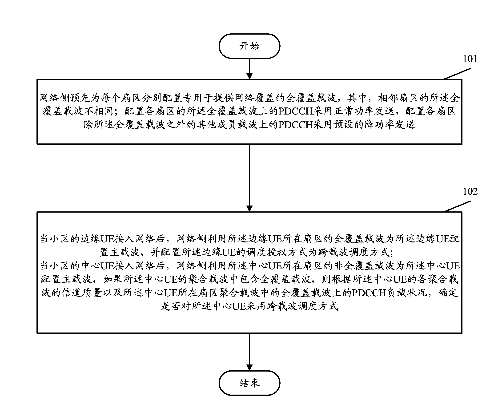
[0017] The core idea of ​​the present invention is: for each sector, set a full-coverage carrier dedicated to providing network coverage, and make the full-coverage carriers of adjacent sectors different; The PDCCH channel of the non-full coverage carrier is transmitted with reduced power; the full coverage carrier of each sector is mainly responsible for providing PDCCH resources for the scheduling of UEs at the sector edge, so as to reduce the inter-PDCCH interference at the sector edge and improve the received SNR of the PDCCH channel At the same time, because the power of the PDCCH on the non-full coverage carrier is only reduced, that is, the power of the traffic channel of the non-full coverage carrier is not reduced, it can ensure t...


PUM


Abstract

The invention discloses a method for reducing downlink control channel disturbance. The method includes the steps that full coverage carrier waves special for providing network coverage are configured for all sectors respectively in advance, and the full coverage carrier waves of every two adjacent sectors are different; PDCCHs on the full coverage carrier waves of all the configured sectors transmit in a normal power mode, and PDCCHs on other carrier waves except the full coverage carrier waves of all the configured sectors transmit in a power reduction mode; after edge UE gets access to a network, a network side uses the full coverage carrier waves of the sector where the edge UE is located for configuring main carrier waves for the edge UE and sets the dispatch authorization mode as a cross-carrier-wave dispatch mode; after center UE gets access to the network, the non-full coverage carrier waves of the sector where the center UE is located are used for configuring main carrier waves for the center UE, and if aggregation carrier waves of the center UE comprise the full coverage carrier waves, the adoption of cross-carrier-wave dispatch is determined according to channel quality of the aggregation carrier waves and load conditions of the PDCCHs on the full coverage carrier waves. The method can reduce PDCCH channel disturbance among cells and achieve PDCCH load balancing under the condition of not affecting a service channel coverage range.

Description

technical field [0001] The invention relates to mobile communication technology, in particular to a method for reducing downlink control channel interference. Background technique [0002] In the LTE system, a physical downlink control channel (PDCCH, Physical Down Control Channel) is used to authorize traffic channels. In the LTE system of the same-frequency network, the physical downlink control channel (PDCCH, Physical Down Control Channel) of each cell on the same frequency point occupies the same time-frequency resource for data transmission. The PDCCH of the cell edge user equipment (UE) suffers from relatively large interference. In order to take into account the demodulation performance and spectrum efficiency under different interference levels, the standard defines 4 control channel element (Control Channel Element, CCE) aggregation levels to transmit downlink control information (Downlink Control Information, DCI), corresponding to use 1, 2 , 4 and 8 CCEs transm...

Claims


Application Information

Patent Timeline
IPC IPC(8): H04W28/08H04L27/26
CPCY02D30/70
Inventor 马慧生吕征南胡静
Owner POTEVIO INFORMATION TECH
Why Eureka
Try Eureka