

Filter bag pull-up type reciprocating oscillation discharge type centrifugal machine
A centrifuge and filter bag technology, which is used in centrifuges, centrifuges with rotating drums, etc., can solve the problems of incomplete removal of filter cakes, inconvenient production and application, and negative impact on increasing operating costs. The effect of complete removal
- Summary
- Abstract
- Description
- Claims
- Application Information
AI Technical Summary
Problems solved by technology
Method used
Image

Examples
Embodiment
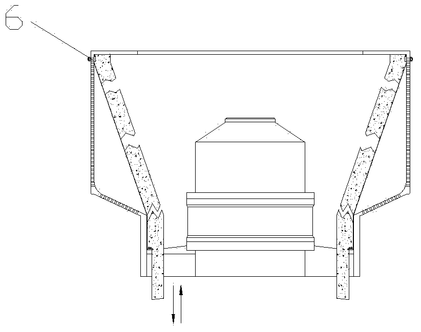
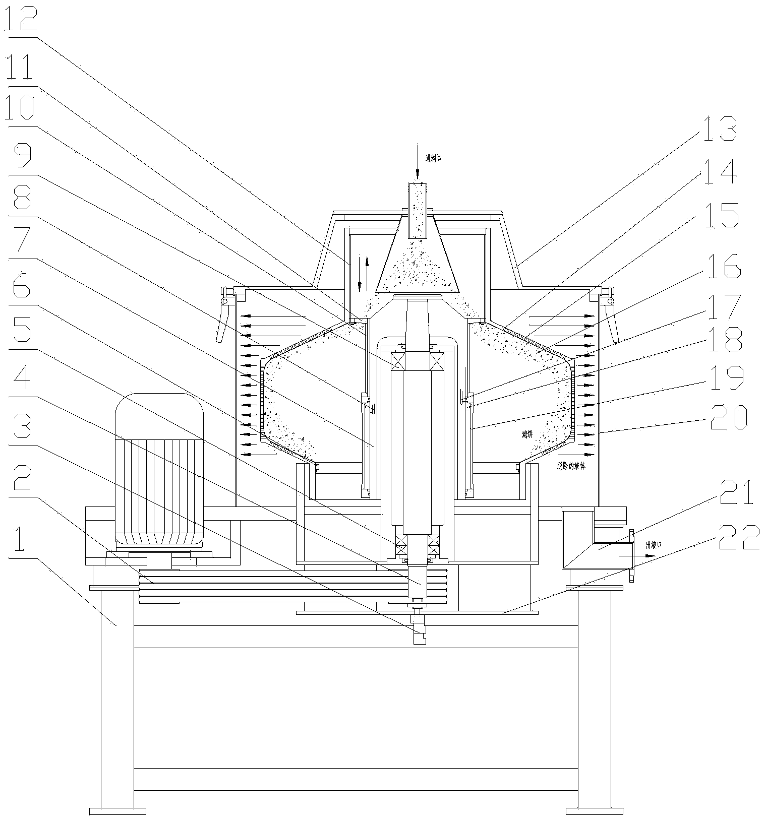
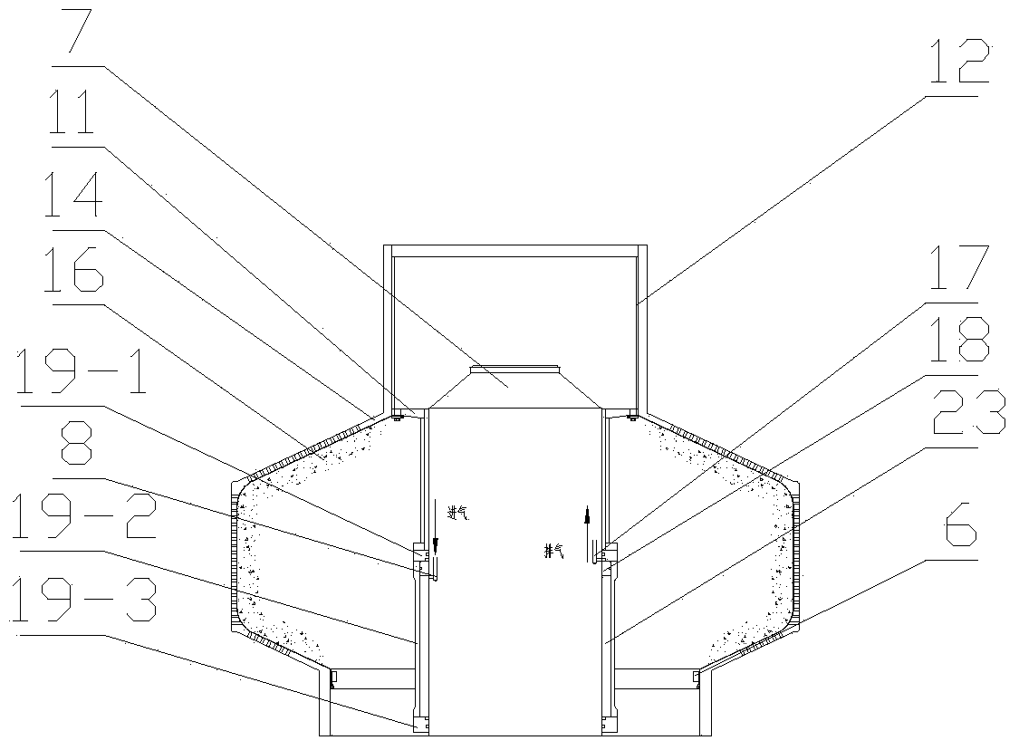
[0021] Example: Combined Figure 2-5 , the filter bag pull-up type reciprocating oscillating discharge type centrifuge of the present embodiment, it comprises:
[0022] Frame 1, a cylindrical shell 20 is fixed on the bottom plate of the frame, and a hollow drum 14 driven by a power mechanism is set in the cylindrical shell, and the drum 14 is an upper column section-upper cone section-middle column section -Five-segment composite vertical structure of the lower cone section-lower column section, wherein the walls of the upper cone section, middle column section, and lower cone section have holes, the inner diameter of the upper column section is the smallest, the inner diameter of the middle column section is the largest, and the inner diameter of the lower column section is larger than The inside diameter of the upper column.
[0023] In the specific setting, the diameter of the upper column section is the smallest, and no holes are opened on the column wall. The inner diam...
PUM
 Abstract
Description
Claims
Application Information