
Rivet conveying mechanism of full-automatic rivet attaching machine

A technology of conveying mechanism and button sewing machine, which is applied in the field of automatic pneumatic button sewing machine, which can solve the problems of high failure rate and U-shaped rivet stuck, and achieve the effect of low failure rate and convenient maintenance and operation

Active Publication Date: 2014-06-18
东莞市恒兴隆实业有限公司
View PDF6 Cites 6 Cited by
  • Summary
  • Abstract
  • Description
  • Claims
  • Application Information

AI Technical Summary

Problems solved by technology

[0009] In order to solve the problem that the existing rivet conveying mechanism of the fully automatic button sewing machine is likely to cause U-shaped rivets to be stuck and have a high failure rate, the present invention provides a rivet conveying mechanism of the fully automatic button sewing machine. The rivet conveying mechanism adopts the structure of conveying turntable and control gate, which can better adapt to various specifications of rivets. There will be no (or less) U-shaped rivet stuck phenomenon during operation, and it has low failure rate and easy maintenance operation. Convenient features, able to meet the needs of customers, worthy of promotion and use

Method used


Image

  • Rivet conveying mechanism of full-automatic rivet attaching machine
  • Rivet conveying mechanism of full-automatic rivet attaching machine
  • Rivet conveying mechanism of full-automatic rivet attaching machine

Examples


Embodiment Construction

[0028] The present invention will be further described below in conjunction with accompanying drawing:

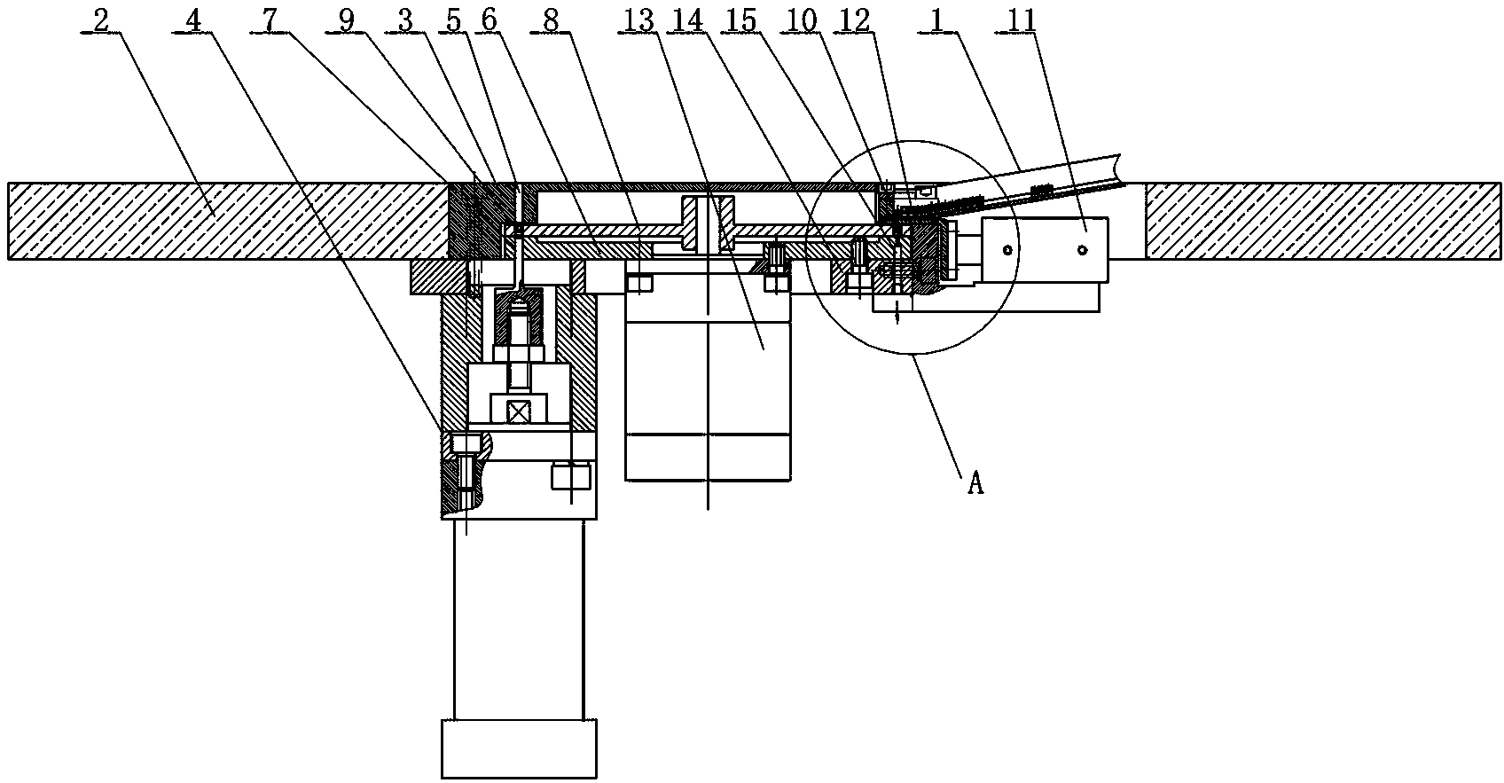
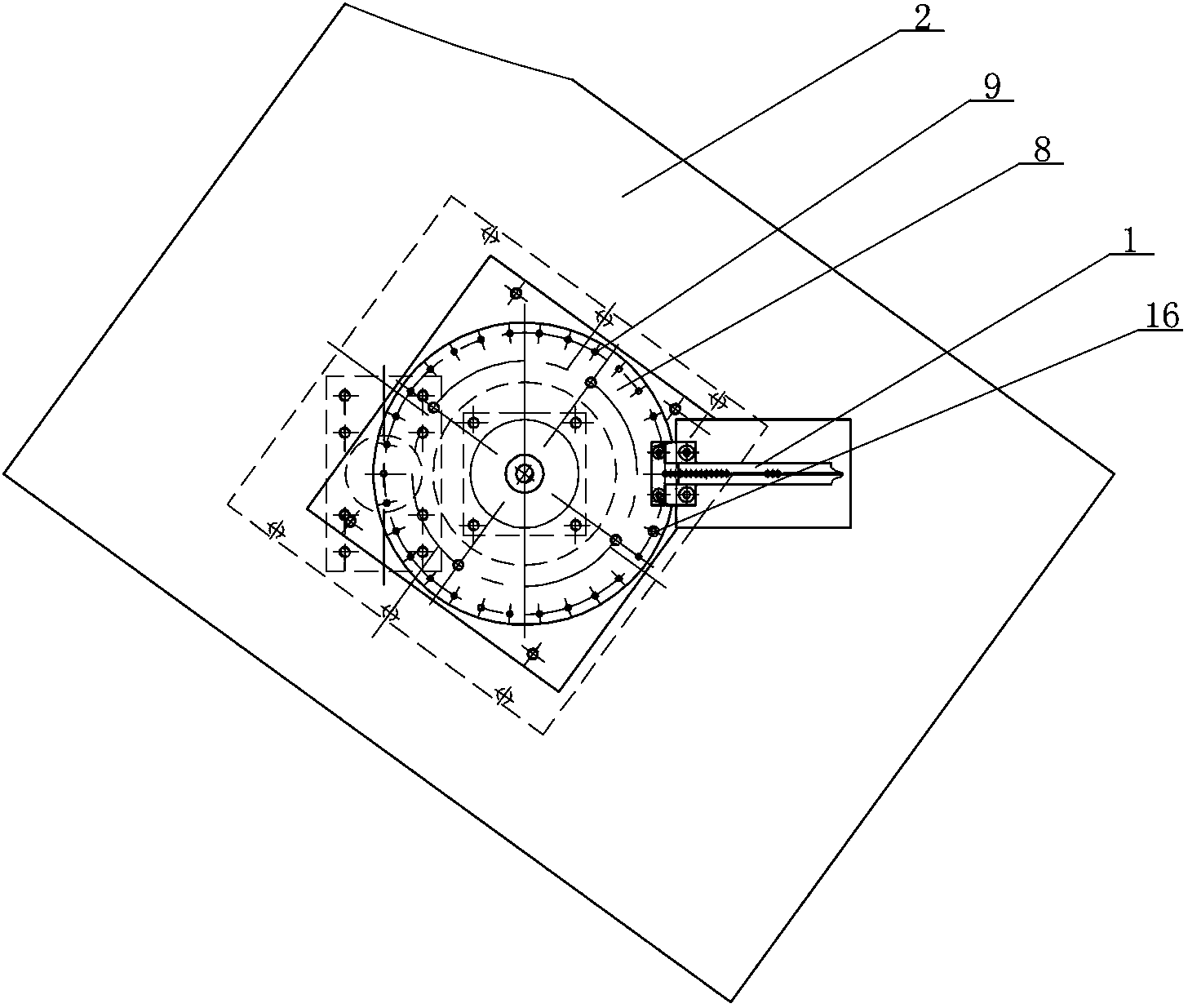
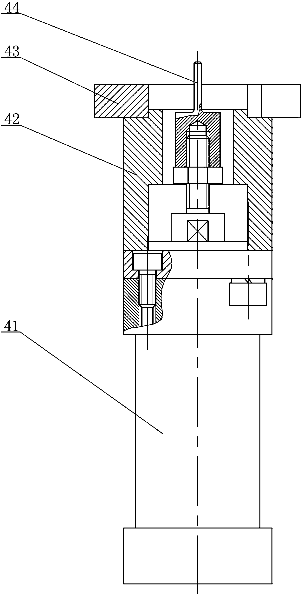
[0029] Depend on Figure 1-Figure 7 As shown, the rivet conveying mechanism of the automatic button sewing machine includes a slideway 1 and a workbench 2. The slideway 1 includes an arrangement vertical plate 101 and a vibrating bottom plate 102, and the workbench 2 is fixed with an upper cover plate 3 and the lower punch assembly 4, the upper cover plate 3 is provided with an upper rivet hole 5, the upper cover plate 3 and the lower punch assembly 4 are provided with a wheel base 6, and the wheel base 6 is provided with an upper rivet The lower rivet hole 7 corresponding to the hole 5, the conveying wheel 8 that can rotate at an equal angle is installed on the wheel base 6, and the edge circumference of the transporting wheel 8 is equally provided with several through holes 9 through which U-shaped rivets can freely pass. The end of the vibrating bottom plate 102 is prov...


PUM


Abstract

The invention relates to a rivet conveying mechanism of a full-automatic rivet attaching machine. The rivet conveying mechanism of the full-automatic rivet attaching machine mainly solves the problems that the existing rivet conveying mechanism of the full-automatic rivet attaching machine is apt to get stuck by U-shaped rivets and the fault rate is high. The rivet conveying mechanism of the full-automatic rivet attaching machine is characterized in that a wheel disc base (6) is arranged between an upper cover plate (3) and a lower punching head assembly (4), and a plurality of through holes (9) through which the U-shaped rivets can freely pass are equidistantly formed in the peripheral circumference of a conveying wheel disc (8); a rivet falling hole (10) which can only hold one U-shaped rivet is formed in the end of a vibrating bottom plate (102), and the rivet falling hole (10) corresponds to another one through hole (9) in the conveying wheel disc (8) at the same time when a lower rivet hole (7) corresponds to a through hole (9) in the conveying wheel disc (8). The rivet conveying mechanism of the full-automatic rivet attaching machine can better adapt to rivets with different specifications, can prevent or reduce the phenomenon that the rivet conveying mechanism gets stuck by the U-shaped rivets, has the characteristics of low fault rate and convenience in maintenance and operation, can meet the demands of customers and is worthy of being popularized and used.

Description

technical field [0001] The invention relates to a fully automatic pneumatic button sewing machine, in particular to a rivet conveying mechanism of the fully automatic button sewing machine. Background technique [0002] With the improvement of living conditions, people's demand for daily necessities such as clothing, shoes, hats, bags, etc. is becoming more and more diversified, and a large number of button decorations have appeared in the clothing, shoes, hats, and bags industries. Because the rivets in the current market are various and the button decorations with various specifications are still relying on manual and semi-automatic operations, they are far from meeting the needs of the market. [0003] The existing fully automatic button sewing machine is mainly composed of an upper vibrating plate assembly, an upper punch assembly, a lower vibrating plate assembly, a lower punch assembly, and a rivet conveying mechanism. The riveting of bead)-shaped decorations is taken...

Claims


Application Information

Patent Timeline
IPC IPC(8): B21J15/32
Inventor 沈永松
Owner 东莞市恒兴隆实业有限公司
Learn More