Clamping device

A technology of clamping device and clamping block, which is applied in the direction of auxiliary devices, auxiliary welding equipment, welding/cutting auxiliary equipment, etc., can solve the problems of large space occupied by welding fixtures, inconvenient control operation, high manufacturing cost, etc., to achieve The structure is simple, the space occupied is small, and the effect of reducing the production cost

Active Publication Date: 2014-06-18
BEIQI FOTON MOTOR CO LTD
View PDF5 Cites 15 Cited by
  • Summary
  • Abstract
  • Description
  • Claims
  • Application Information

AI Technical Summary

Problems solved by technology

[0005] The purpose of the present invention is to provide a clamping device to overcome the need to use different welding fixtures for clamping and welding parts of different heights in the prior art, resulting in a large space occupied by the welding fixtures, which is prone to interference problems, Inconvenient control operation, high manufacturing cost and other problems

Method used


Image

  • Clamping device
  • Clamping device
  • Clamping device

Examples


Embodiment 1

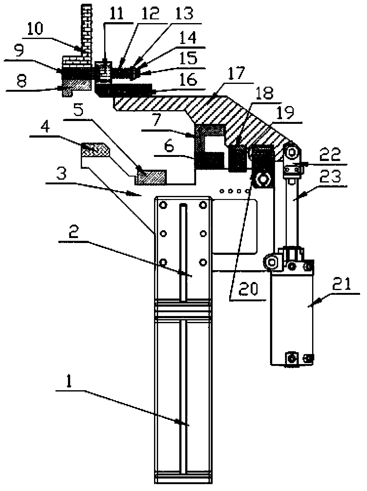
[0027] Such as figure 1 As shown, the clamping device of this embodiment includes a support seat, a lower support plate 3, an upper support plate 17 and a telescopic drive mechanism; the support seat includes a base 1 and an L-shaped plate 2, and the L-shaped plate 2 is fixed on the base by fastening bolts 1. The upper and lower support plates 3 are fixed on the L-shaped plate 2 by fastening bolts. One end of the lower support plate 7 is rotatably connected to the upper support plate 17, and the other end is provided with the first lower clamping block 4; telescopic drive device Select the air cylinder, the cylinder barrel 21 of the cylinder is connected with the lower support seat 3, the piston rod 23 of the cylinder is connected with the upper support seat 17, and the joints between the cylinder and the lower support seat 3 and the upper support seat 17 are located at the lower support seat 3 and the upper support seat. Near the junction of seat 17.

[0028] The upper suppo...

Embodiment 2

[0037] Such as figure 1 As shown, the difference between the clamping device of this embodiment and that of Embodiment 1 is that the upper clamping block fixing base 9 is a 3-prism, each side of which is provided with an upper clamping block, and the corresponding concave of the rotating support The groove is triangular; the rotary chuck in this case has three upper clamping blocks of different sizes, but its manufacturing cost and difficulty are greater than that of Example 1, so different types of rotary chucks should be selected according to the needs of the actual situation. Similarly, the rotary chuck can also be provided with other numbers.

[0038] The specific connection method between the telescopic drive mechanism of this embodiment and the lower support plate 3 and the upper support plate 17 can also be changed, and the materials and connection methods of each component should also be selected according to the actual situation.


PUM


Abstract

The invention relates to the field of a welding fixture and particularly discloses a clamping device. The clamping device comprises a supporting seat, a lower supporting plate, an upper supporting plate and a telescopic driving mechanism; the lower supporting plate is fixed on the supporting seat; one end of the lower supporting plate is rotatably connected with the upper supporting plate and the other end of the lower supporting plate is provided with a first lower clamping block; both ends of the telescopic driving mechanism are respectively connected with the lower supporting plate and the upper supporting plate; the upper supporting plate is provided with a spin chuck; the spin chuck is provided with a plurality of upper clamping blocks with different sizes; and the positions of the upper clamping blocks correspond to the positions of the first lower clamping blocks. According to the invention, universality of the clamping device on clamping and welding of parts with different heights; on the premise of ensuring part welding accuracy and part welding quality, the clamping device has a simple structure and is convenient to operate, the number of tools is reduced, an occupied space is small, influence on soldering plier operation is low, the welding repair operation is carried out a little, production cost is greatly reduced and production efficiency is effectively improved.

Description

technical field [0001] The invention relates to the field of welding fixtures, in particular to a clamping device capable of freely switching between different clamping modes. Background technique [0002] The welding fixture is an important process equipment that needs to be used in the welding process of the car body. The main function of the welding fixture is: the car body is composed of several parts with different sizes, shapes and thicknesses, and various parts need to be welded. The parts are connected to form the body, and the parts will have dimensional deviations during the welding process. In order to solve the dimensional deviations of the parts during the welding process, it is necessary to use welding fixtures for clamping and positioning during welding to ensure the welding accuracy of the parts. [0003] For the existing welding fixtures, when two parts with different heights need to be clamped and welded sequentially, due to the limitation of the position o...

Claims


Application Information

Patent Timeline
Patent Type & Authority Applications(China)
IPC IPC(8): B23K37/053
CPCB23K37/0435
Inventor 陈玥高志金汪勤
Owner BEIQI FOTON MOTOR CO LTD
Why Eureka
Try Eureka