Buffering roller device

A technology of rollers and roller racks, applied in the directions of rollers, transportation and packaging, conveyors, etc., can solve the problems of high cost of use, smashing and falling off of the glue layer, poor glue injection, etc., so as to reduce the maintenance cost and prolong the use. Longevity and good buffering effect

Inactive Publication Date: 2014-06-18
安阳县安达机械有限责任公司
View PDF0 Cites 3 Cited by
  • Summary
  • Abstract
  • Description
  • Claims
  • Application Information

AI Technical Summary

Problems solved by technology

Most designers have carried out some modifications at the blanking point, and the effect is not very satisfactory. For example, casting rubber on the roller and thickening the buffer rubber layer, although it has some effects, it is not very obvious, and the service life is short. High cost (casting cost)
The reason is that the rubber

Method used


Image

  • Buffering roller device
  • Buffering roller device

Examples


Embodiment Construction

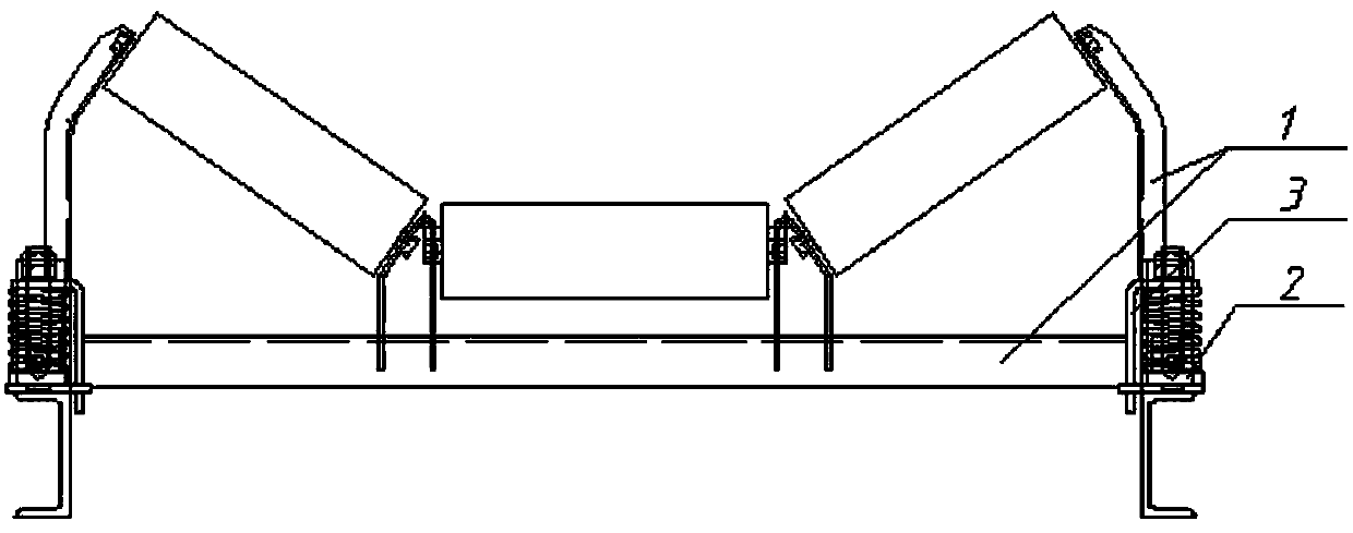
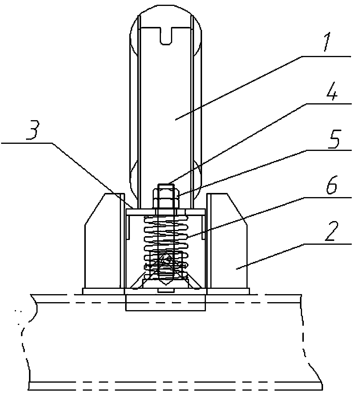
[0010] Such as figure 1 , figure 2 The buffer idler device shown includes a roller frame 1, a U-shaped groove 2, a support frame 3 and an elastic device. The supporting frame 3 is connected with the idler frame 1.

[0011] Such as figure 2 As shown, the elastic device includes a spring 6, a bolt 4 and an adjusting nut 5, the bolt 4 passes through the support frame 3 and is fixed at the bottom of the U-shaped groove 2, and the spring 6 is sleeved on the bolt 4 at the bottom of the support frame in the U-shaped groove, The nut 5 is screwed on the bolt 4 at the upper end of the support frame.

[0012] When in use, adjust the adjusting nut 5 to an appropriate position according to the impact force of the blanking, and give the spring 6 a suitable preload. When the belt conveyor is subjected to the impact force of the blanking, the idler frame 1 is supported The frame 3 transmits the impact force to the spring 6. At this time, the spring 6 rebounds and plays a good buffering ...


PUM


Abstract

The invention discloses a buffering roller device, and the buffering roller device comprises a roller frame, a U-shaped slot, a support frame and an elastic device, wherein the U-shaped slot is fixed to the lower end of the roller frame; the elastic device is arranged in the U-shaped slot and connected with the roller frame through the support frame. The buffering roller device not only has excellent buffering effect but also it has low cost and long service life, and is convenient to use.

Description

technical field [0001] The invention relates to a device used for the position of the material drop point of a belt conveyor, used for supporting idler rollers, and acting as a buffer. Background technique [0002] During the production process, at the blanking place of the belt conveyor, various materials fall onto the belt from a high place, which has a great impact on the belt, especially some blocky materials. The impact of the material will not only shorten the service life of the belt and roller, but also increase the maintenance cost of the belt conveyor. Most designers have carried out some modifications at the blanking point, and the effect is not very satisfactory. For example, casting rubber on the roller and thickening the buffer rubber layer, although it has some effects, it is not very obvious, and the service life is short. High cost (casting cost). The reason is that the rubber layer on the roller wears quickly on the long-term rotating roller, and it is ea...

Claims


Application Information

Patent Timeline
IPC IPC(8): B65G39/14B65G15/60
Inventor 王文政
Owner 安阳县安达机械有限责任公司
Why Eureka
Try Eureka