Annular hydraulic cylinder

A ring-shaped hydraulic cylinder and hydraulic cylinder technology are applied in the field of hydraulic cylinders to achieve the effects of easy manufacture, compact structure and good sealing performance

Active Publication Date: 2014-06-18
深圳市贝特尔机器人有限公司 +1
View PDF7 Cites 3 Cited by
  • Summary
  • Abstract
  • Description
  • Claims
  • Application Information

AI Technical Summary

Problems solved by technology

[0005] The invention aims to solve the problem of direct output torque in the field of hydraulic cylinders, and designs an annular hydraulic cylinder that is easy to manufacture, compact in structure, low in failure rate, good in sealing performance and good in dynamic characteristics

Method used


Image

  • Annular hydraulic cylinder
  • Annular hydraulic cylinder
  • Annular hydraulic cylinder

Examples


Embodiment Construction

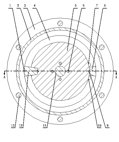
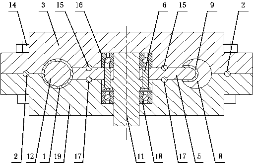
[0036] Below in conjunction with accompanying drawing, the present invention is further described: as Figure 1-15 As shown, a ring-shaped hydraulic cylinder is composed of an upper end cover 3, a hydraulic cylinder oil chamber 4, a lower end cover 19, an annular piston rod 5, a piston 12, a fixed stopper 8 and an output shaft 11;

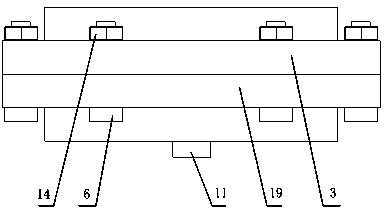
[0037] Such as figure 1 with figure 2 As shown, the upper end cover 3 and the lower end cover 19 are connected by six bolts 13 and nuts 14 uniformly distributed around the circumference. Such as image 3 As shown, the hydraulic cylinder oil chamber 4 is composed of the upper end cover 3 and the lower end cover 19, and the first sealing ring 2 is used to seal between the upper end cover 3 and the lower end cover 19.

[0038] Such as figure 1 As shown, the fixed block 8 is affixed to the inner wall of the hydraulic cylinder oil chamber 4, the fixed block 8 is in motion with the annular piston rod 5, the piston 12 is affixed to the annular piston...


PUM


Abstract

An annular hydraulic cylinder comprises an upper end cover (3) and a lower end cover (19). The upper end cover (3) and the lower end cover (19) are connected through six bolts (13) and six nuts (14), wherein the bolts and the nuts are evenly and circumferentially distributed. An annular hydraulic cylinder oil cavity (4), an annular piston rod (5), a piston (12) and a fixed stopping block (8) are arranged in the space between the upper end cover (3) and the lower end cover (19). The annular hydraulic cylinder further comprises an output shaft (11), wherein one end of the output shaft is connected with the upper end cover (3), and the other end of the output shaft sequentially penetrates through the annular piston rod (5) and the lower end cover (19) to stretch out of the lower end cover. The annular hydraulic cylinder has the advantages of being convenient to manufacture, compact in structure, low in fault rate, good in sealing performance and good in dynamic property.

Description

technical field [0001] The invention relates to the technical field of hydraulic cylinders, in particular to an annular hydraulic cylinder. Background technique [0002] The hydraulic cylinder is the core component of the hydraulic control system and is widely used in industry. It can convert the small power input by the motor into the high power output by the hydraulic pressure, so as to output high power and stability to the equipment. [0003] At present, the rack structure swing cylinder is commonly used to convert the linear reciprocating motion of the traditional hydraulic cylinder into the swing motion. The principle of the swing cylinder is to convert the reciprocating motion of the hydraulic cylinder into the positive and negative directions of the gear shaft through the gear rack. Swing and rotate, while converting the thrust of the reciprocating hydraulic cylinder into the output torque of the gear shaft. [0004] However, the failure rate of the rack-and-pinion ...

Claims


Application Information

Patent Timeline
Patent Type & Authority Applications(China)
IPC IPC(8): F15B15/08F15B15/20F16J15/16
Inventor 蒋林胡金郑开柳吴若麟晏晚君梅鹏张宏伟胡琪郑翠郑洁肖俊刘晓磊金祖飞邹竞刚赵慧刘白雁雷斌曾镛
Owner 深圳市贝特尔机器人有限公司
Why Eureka
Try Eureka