
A water medium coupler and its internal pressure relief method

A coupling and water medium technology, applied in the direction of functional valve type, fluid transmission device, safety valve, etc., can solve problems such as troubles, achieve good sealing effect, and prevent the leakage of working water and gas

Active Publication Date: 2016-03-23
SHANGHAI TIANJIAO ELECTROMECHANICAL SCI & TECH
View PDF4 Cites 0 Cited by
  • Summary
  • Abstract
  • Description
  • Claims
  • Application Information

AI Technical Summary

Problems solved by technology

For this reason, although this method can solve the problem of internal vaporization pressure, water must be continuously removed when exhausting, and liquid must be continuously replenished at the same time, which is very troublesome

Method used


Image

  • A water medium coupler and its internal pressure relief method
  • A water medium coupler and its internal pressure relief method
  • A water medium coupler and its internal pressure relief method

Examples


Embodiment 1

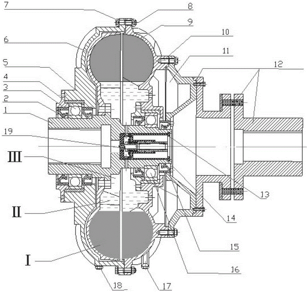
[0098] A water medium coupler, the water medium coupler sequentially includes: an input coupling assembly connected to a motor at an input end, a rotating casing for transmission, a turbine and a pump wheel arranged in the rotating casing for transmission, forming The ring-shaped airtight auxiliary chamber between the rotary housing and the input coupling assembly passes through the hollow turbine shaft at the input end and the output end. Water is used in the coupling cavity, that is, the space formed by the pump wheel and the rotary housing. medium. The input coupling part 12 consists of the input coupling and associated elastic connectors.

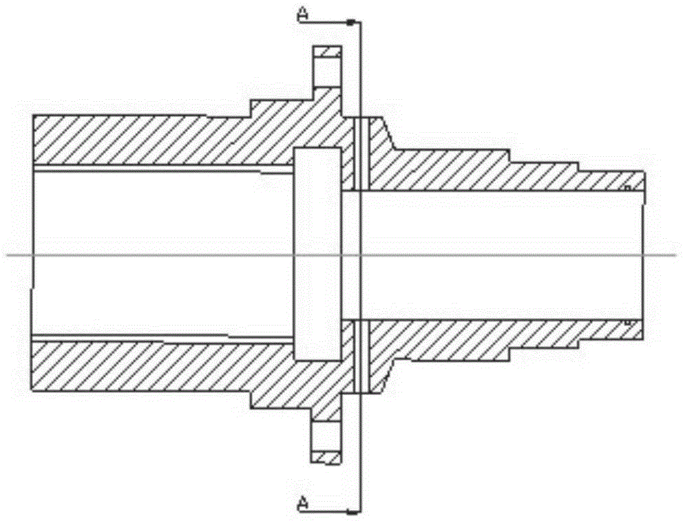
[0099] The turbine shaft 1 is hollow, and an internal relief valve 19 is built in the hollow part of the connection end of the turbine shaft 1 with the input coupling assembly. The auxiliary chamber 11 is a ring formed between the rotary housing 5 and the input coupling assembly 12. The root of the pump wheel 9 is provided with a throu...


PUM


Abstract

The invention provides an aqueous medium coupling and an internal pressure release method thereof. The aqueous medium coupling comprises an input coupling assembly arranged at the input end and connected with a motor. A rotary shell is connected with a pump wheel so that a turbine can be arranged in the rotary shell to form an annular sealed chamber between the rotary shell and the pump wheel. The coupling also comprises a hollow turbine shaft, and aqueous media are used in a coupling cavity which is a space formed by the pump wheel and the inside of the rotary shell. The coupling is characterized in that the turbine shaft is hollow, an internal pressure release valve is arranged in the hollow portion of the turbine shaft, when the coupling is overloaded and heated, water is heated and vaporized, and when pressure rises and exceeds a preset value, the internal pressure release valve automatically releases gas or steam to prevent the gas pressure from further rising. The aqueous medium coupling and the internal pressure release method are particularly suitable for scraper conveyers, belt conveyers, reverse loaders, coal ploughs, crushing machines and the like with high flame-proof and anti-explosion requirements for couplings in mine enterprises and the like.

Description

technical field [0001] The present invention relates to the field of hydraulic transmission and automation, in particular, the present invention relates to a water medium coupling and its internal pressure relief method. Scraper conveyors, belt conveyors, reloaders, coal plows, crushers, etc. with high requirements for fire prevention and explosion protection. Background technique [0002] In mining enterprises such as coal mines, a large number of scraper conveyor equipment is required. The role of equipment such as scraper conveyors is not only to transport coal and materials, but also used for the running track of coal mining machines. Therefore, scraper conveyors have become indispensable main equipment in modern coal mining processes. Due to the frequent start-up of the scraper conveyor, large changes in start-up and working load, and serious stalling phenomenon, and because of its narrow space and harsh environment, currently, torque-limiting hydraulic or water medium...

Claims


Application Information

Patent Timeline
Patent Type & Authority Patents(China)
IPC IPC(8): F16H41/04F16H41/24F16H41/30F16K17/06
CPCF16H41/24F16H41/30F16K17/06F16K17/383
Inventor 黄刘琦师好智袁咏雷
Owner SHANGHAI TIANJIAO ELECTROMECHANICAL SCI & TECH
Learn More