Braking system testing equipment and method

A technology of braking system and testing method, which is applied in the direction of railway vehicle testing, etc., can solve problems such as comprehensive testing without the convenience of KE distribution valve performance, and achieve the effect of simple testing and guaranteed reliability

Active Publication Date: 2014-06-18
CHANGCHUN RAILWAY VEHICLE FACILITIES
View PDF5 Cites 15 Cited by
  • Summary
  • Abstract
  • Description
  • Claims
  • Application Information

AI Technical Summary

Problems solved by technology

However, the existing technology has not yet provided a test plan and equipment that can efficiently and easily comprehensively test the performance of the KE distribution valve.

Method used


Image

  • Braking system testing equipment and method
  • Braking system testing equipment and method
  • Braking system testing equipment and method

Examples


Embodiment Construction

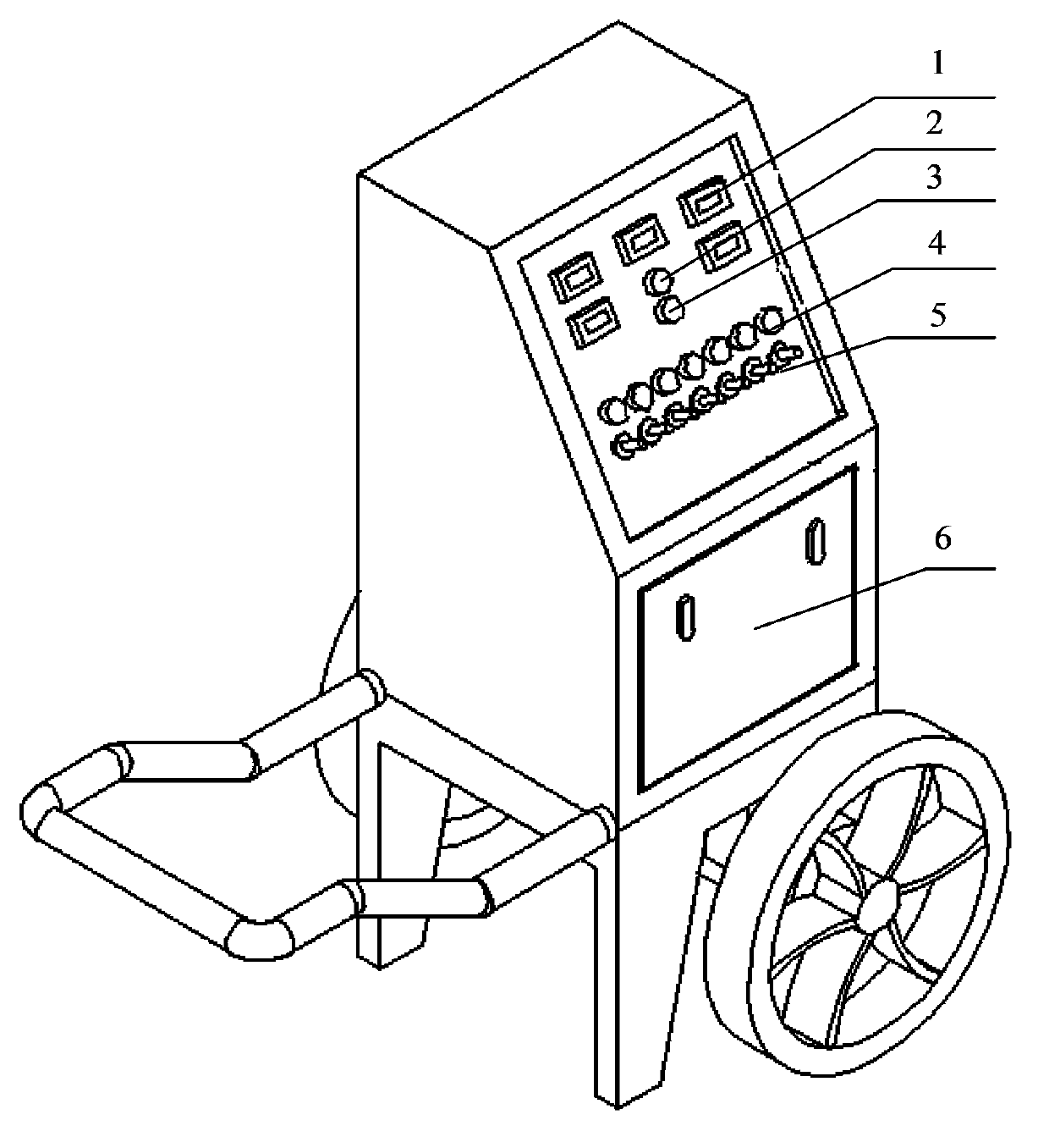
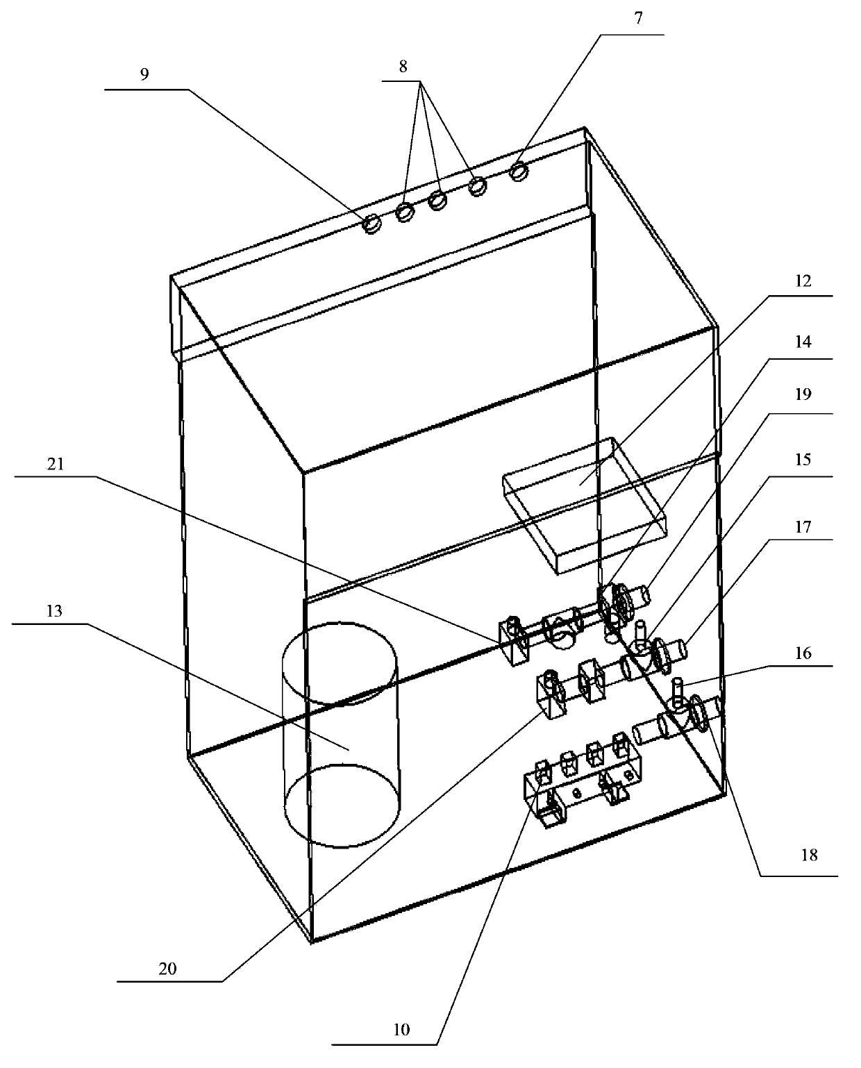
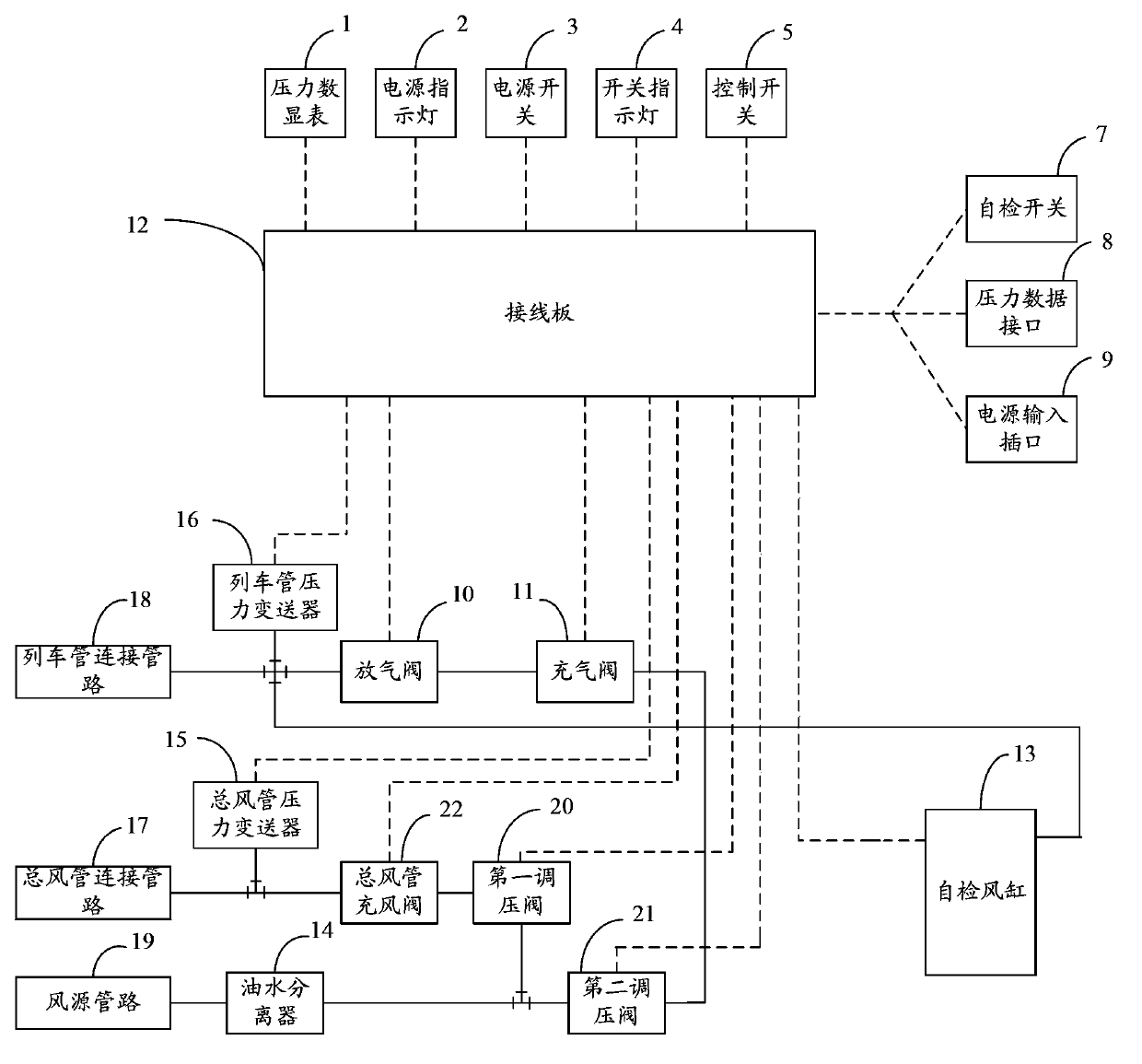
[0027] figure 1 An external structural diagram of the braking system testing equipment provided in Embodiment 1 of the present invention, figure 2 The internal structure diagram of the braking system testing equipment provided by Embodiment 1 of the present invention. image 3 It is a connection principle diagram of the braking system testing equipment provided by Embodiment 1 of the present invention.

[0028] Such as Figure 1-3 As shown, the brake system testing equipment includes: a main air pipe connecting pipeline 17, a train pipe connecting pipeline 18, an air source pipeline 19, an air cylinder pressure transmitter and a control module.

[0029] The interface of the main air duct connecting pipeline 17 is used to connect the main air duct of the vehicle to be tested, and the main air duct connecting pipeline 17 is equipped with a main air duct pressure transmitter 15 for collecting the pressure value in the main air duct; The interface of the train pipe connecting ...


PUM


Abstract

The invention provides a braking system testing equipment and method. The braking system testing equipment comprises a general air pipe connection pipeline, a train pipe connection pipeline, an air source pipeline and a control module, wherein a connector of the general air pipe connection pipeline is used for connecting a general air pipe of a vehicle to be detected; the pipeline is provided with a general air pipe pressure transmitter; a connector of the train pipe connection pipeline is used for connecting a train pipe of the vehicle to be detected and the pipeline is provided with a train pipe pressure transmitter and is further provided with a deflating valve; a connector of the air source pipeline is used for connecting an air source; the air source pipeline is communicated with the general air pipe connection pipeline by a first pressure adjusting valve and the general air pipe and is communicated with the train pipe pressure transmitter by a second pressure adjusting valve and an inflating valve; the control module is used for controlling the opening and the closing of the first pressure adjusting valve, the second pressure adjusting valve, the inflating valve and the deflating valve and obtaining pressure values of the general air pipe pressure transmitter and the train pipe pressure transmitter to be used as testing results. The braking system testing equipment and method can be used for carrying out an efficient, simple and convenient, and comprehensive test on a braking system and the reliability of operating the vehicle braking system is guaranteed.

Description

technical field [0001] The invention relates to a pneumatic equipment testing technology, in particular to a braking system testing equipment and method. Background technique [0002] The brake system is a necessary part of a railway passenger car. Its braking principle is to use the change of gas pressure to drive the brake parts to act when the pressure in the air cylinder is released, and to brake the axle or wheel set, and the pressure in the air cylinder rises. When driving the brake part to return, release the brake. The existing braking system mainly includes a brake air cylinder, an auxiliary air cylinder and an additional air cylinder, which are respectively connected with the main air pipe and the train pipe arranged on the vehicle, and control the action of the valve body in the pipeline to realize the internal pressure of the air cylinder. rise and release. [0003] In order to ensure the reliability of the operation of the braking system, it is necessary to de...

Claims


Application Information

Patent Timeline
IPC IPC(8): G01M17/08
Inventor 马冬梅郭福海刘锦辉
Owner CHANGCHUN RAILWAY VEHICLE FACILITIES
Why Eureka
Try Eureka