
AFM probe device

An atomic force microscope and probe technology, which is applied in measurement devices, scanning probe technology, scanning probe microscopy, etc. The effect of saving manpower and time loss, improving success rate and improving utilization rate

Active Publication Date: 2014-06-18
SHANGHAI HUALI MICROELECTRONICS CORP
View PDF13 Cites 9 Cited by
  • Summary
  • Abstract
  • Description
  • Claims
  • Application Information

AI Technical Summary

Problems solved by technology

Because the detection needle is small and light, it increases the operation difficulty of the needle replacement process. During the needle replacement process, it is easy to fail the needle replacement of the detection needle due to the misplacement or drop of the detection needle. At this time, the staff needs to suspend the operation of the machine. Operation, detection and maintenance of the atomic force microscope machine, additional time cost
[0004] It can be seen from the above that in the existing technology, the uncertainty of changing the needle of the atomic force microscope is likely to delay the testing process and increase unnecessary manpower burden

Method used


Image

  • AFM probe device
  • AFM probe device
  • AFM probe device

Examples


no. 1 example

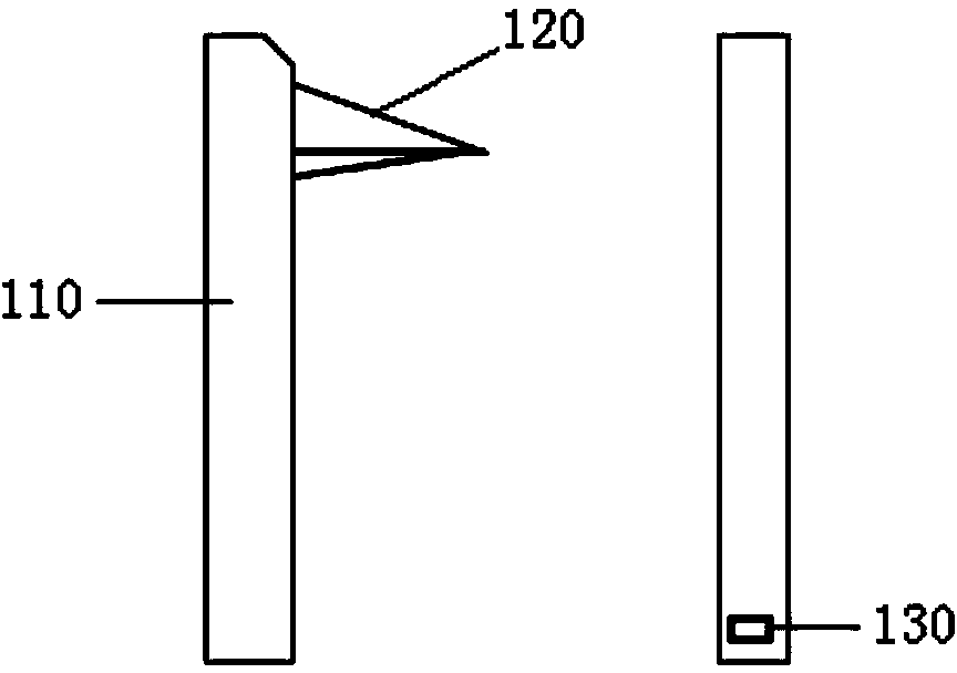
[0027] Please refer to Figure 3 to Figure 6 , the atomic force microscope probe device provided in this embodiment includes a probe pin and a probe base. The probe includes a micro-cantilever 110 fixed on the probe base and a needle tip 120 arranged at one end of the micro-cantilever. The surface of the microcantilever 110 on which the needle tip 120 is placed is taken as the front side, and the surface opposite to the needle tip 120 is called the back side. In this embodiment, the microcantilever 110 is fixed in the probe holder by vacuum adsorption. Specifically, the probe holder includes an adsorption piece 210, which has an adsorption surface S, and an air guide groove 220 is opened on the adsorption surface S, and the air guide groove 220 communicates with a vacuum pumping component (not shown in the figure), and the vacuum pumping component is used to The negative pressure is generated so that the back of the micro-cantilever 110 is closely adsorbed to the adsorption ...

no. 2 example

[0033] Please refer to Figure 7a , 7b and Figure 8 with Figure 9, which shows an atomic force microscope probe device according to another embodiment of the present invention. The probe device includes a probe needle and a probe base. The probe includes a micro-cantilever 110 fixed on the probe base and a needle tip 120 arranged at one end of the micro-cantilever. The surface of the microcantilever 110 on which the needle tip 120 is placed is taken as the front side, and the surface opposite to the needle tip 120 is called the back side. The microcantilever 110 is fixed in the probe holder by vacuum adsorption. The probe base includes an adsorption piece 210, which has an adsorption surface S, and an air guide groove 220 is opened on the adsorption surface S, and the air guide groove 220 communicates with a vacuum pumping component (not shown in the figure), and the negative pressure is generated by the vacuum pumping component The back surface of the micro-cantilever ...


PUM


Abstract

The invention discloses an AFM probe device. The AFM probe device comprises a probe and a probe base, wherein the probe comprises a micro-cantilever and a probe tip arranged at one end of the micro-cantilever, and a stepped hole is formed in the surface, opposite to the probe tip, of the micro-cantilever; the probe base comprises an absorption piece and a positioning piece; the absorption piece comprises a vacuum absorption groove and an absorption surface; the vacuum absorption groove is used for allowing the probe to be absorbed on the absorption surface; the positioning piece extends out of the absorption surface, is inserted into the stepped hole and rotates so as to abut against the stepped surface of the stepped hole. According to the AFM probe device, the efficiency of replacing the probe can be improved.

Description

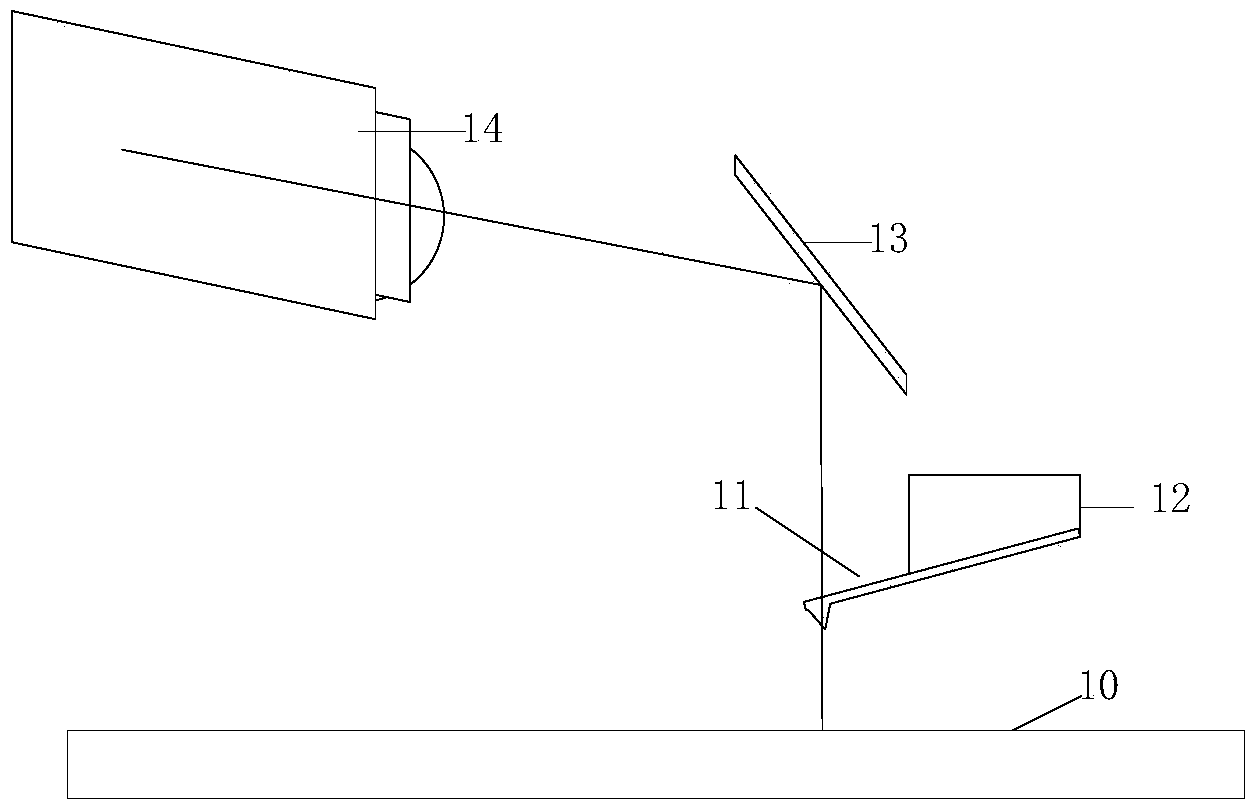
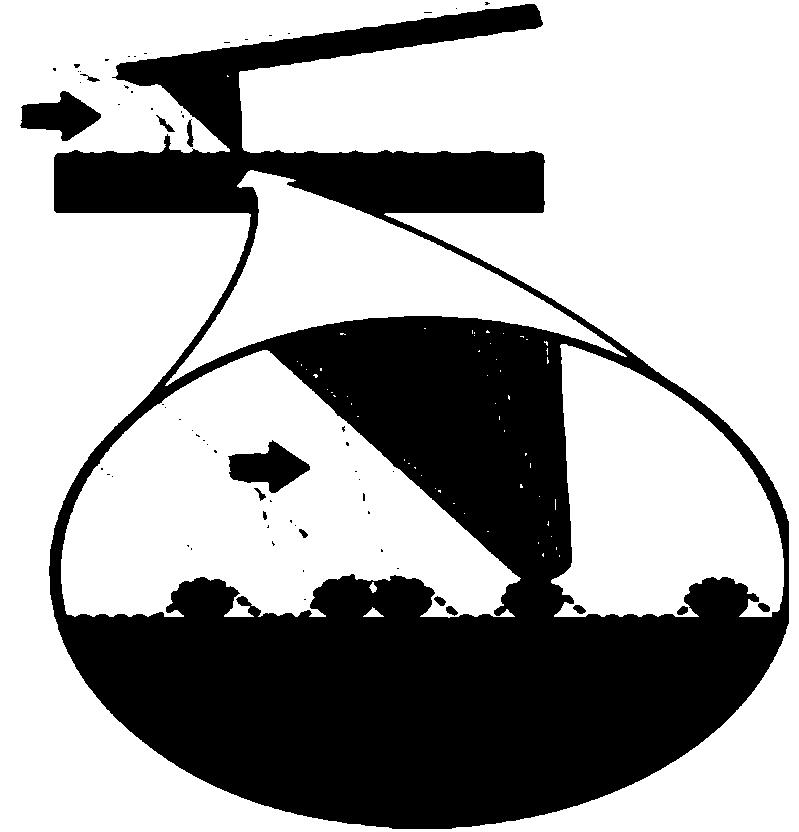
technical field [0001] The invention relates to the technical field of semiconductor testing, in particular to a probe device of an atomic force microscope. Background technique [0002] Nowadays, Atomic Force Microscope (AFM) has been widely used in the testing of semiconductor samples. Its working principle is to detect the extremely weak interatomic interaction between the surface of the sample to be tested and a miniature force-sensitive element (probing needle). To study the surface structure and properties of matter. Such as figure 1 As shown, generally speaking, the probe 11 includes a needle tip and a micro-cantilever, and one end of the micro-cantilever that is extremely sensitive to weak force is fixed on the probe base 12, and the tiny needle tip at the other end of the micro-cantilever is close to the sample 10, when the needle tip is in contact with the sample (Such as figure 2 Shown), because there is a very weak force (attraction or repulsion) between thei...

Claims


Application Information

Patent Timeline
IPC IPC(8): G01Q60/38
Inventor 白英英张守龙王伟
Owner SHANGHAI HUALI MICROELECTRONICS CORP
Learn More