Illumination optical system for beam projector

A technology for lighting optical systems and projectors, applied in the field of optical systems, can solve problems such as difficulty in miniaturization

Inactive Publication Date: 2014-06-18
SAMSUNG ELECTRONICS CO LTD
View PDF8 Cites 23 Cited by
  • Summary
  • Abstract
  • Description
  • Claims
  • Application Information

AI Technical Summary

Problems solved by technology

However, as described above, although the illumination optical system is improved in terms of color reproduction by using a plurality of light emitting diodes and / or laser diodes, the light travels along different paths in the illumination optical system depending on the color of light to be incident on the display panel. path travel, which requires multiple optical components such as lenses and mirrors
When arranging multiple light sources and the lenses and mirrors on different optical paths is implemented in a portable terminal, it is difficult to achieve miniaturization

Method used


Image

  • Illumination optical system for beam projector
  • Illumination optical system for beam projector
  • Illumination optical system for beam projector

Examples


Embodiment Construction

[0027] Hereinafter, various embodiments of the present invention will be described with reference to the accompanying drawings. For the purpose of clarity and conciseness, detailed descriptions of known functions and constructions contained herein will be omitted since they may obscure the subject matter of the present invention.

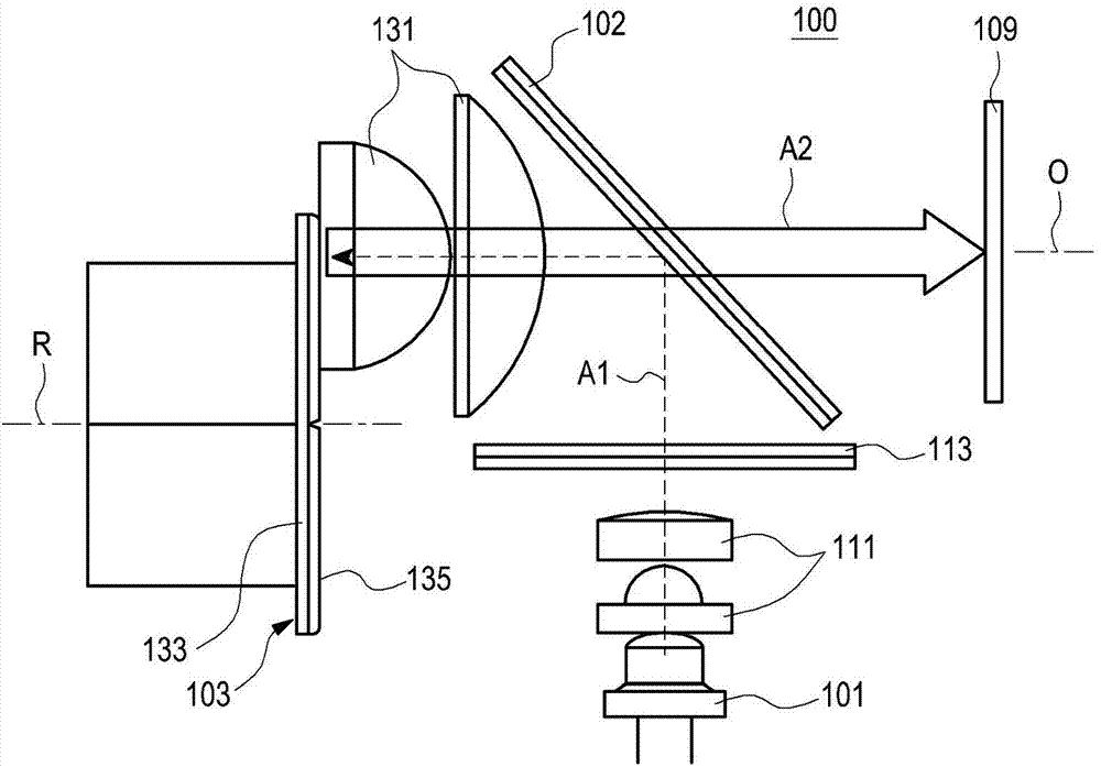
[0028] figure 1 The structure of the illumination optical system 100 of the beam projector is shown. As shown in the figure, the illumination optical system 100 of the beam projector includes a light source 101, a color conversion unit 103 and a dichroic mirror 102, wherein the light emitted from the light source 101 is incident on the color conversion unit 103 through the dichroic mirror 102, The lights having different wavelengths emitted by the color conversion unit 103 travel in opposite directions in the same path to be incident on the display panel 109 . Here, the color of the light is determined according to the frequency of the light. The...


PUM


Abstract

The invention provides an illumination optical system for a beam projector. The illumination optical system for the beam projector includes: a light source; a color conversion unit having at least one fluorescent substance layer that reflects a light from the light source or converts the light emitted from the light source to a wavelength-converted light; and a dichroic mirror that causes the light emitted from the light source to be incident on the color conversion unit. Lights reflected or emitted by the conversion unit and having different wavelengths are incident on a display panel through the same path. In the illumination optical system, a light emitted from one light source can be processed to produce red, green and blue lights which can be in turn incident on the display panel through the same optical path of the light reflected or emitted by the conversion unit.

Description

technical field [0001] The present invention relates generally to an optical device, and more particularly, to an optical system for a beam projector that magnifies an image output from a display panel and projects the magnified image onto a screen superior. Background technique [0002] A beam projector is an optical instrument that uses an optical system and a display panel to achieve magnified images. The size of the image can be adjusted according to the distance between the beam projector and the screen. If a sufficient distance between the beam projector and the screen can be ensured, it is easy to realize a large image with high definition regardless of the size of the display device. [0003] The optical system in the beam projector structure can be divided into illumination optical system and transmission optical system. The illumination optical system means an optical system formed by optical elements arranged on an optical path from a light source to a display ...

Claims


Application Information

Patent Timeline
Patent Type & Authority Applications(China)
IPC IPC(8): G03B21/20F21V9/10G02B26/00F21V9/40
CPCG03B21/20F21V9/08G02B26/008G03B21/206F21V9/10F21V9/45G03B21/204G03B21/2066G03B33/08
Inventor 金容官朴成夏桂溶燦李重基朴重完
Owner SAMSUNG ELECTRONICS CO LTD
Why Eureka
Try Eureka