
Improved touch pen conducting means

A stylus and touch technology, applied in electrical digital data processing, data processing input/output process, instruments, etc., can solve the problems of touch panel inoperability, multi-surface processing cost, TouchPanel failure, etc.

Inactive Publication Date: 2014-06-18
吴振华
View PDF3 Cites 1 Cited by
  • Summary
  • Abstract
  • Description
  • Claims
  • Application Information

AI Technical Summary

Problems solved by technology

Resistive touch panels can be divided into four-wire and five-wire types according to performance and universality. The XY axes of four-wire resistive touch panels are respectively distributed on ITO Film and ITO Glass. When the ITO Film is severely scratched, it will An open circuit will be formed, causing the touch panel to fail to operate
The five-wire touch panel is an improved version of the four-wire touch panel. The entire electric field is evenly established on the ITO Glass. The upper ITO Film is purely a conductor, so when the ITO Film is scratched, only this part cannot be used, and other parts can still be used. action, but if the underlying ITO Glass is damaged, it will cause the failure of the Touch Panel
[0007] To sum up, although the above two ways of making the pen body can achieve the conductive effect, the cost of the pen body is relatively high. Moreover, in order to achieve beautiful colors or patterns, more surface processing costs must be added.

Method used


Image

  • Improved touch pen conducting means
  • Improved touch pen conducting means
  • Improved touch pen conducting means

Examples


Embodiment Construction

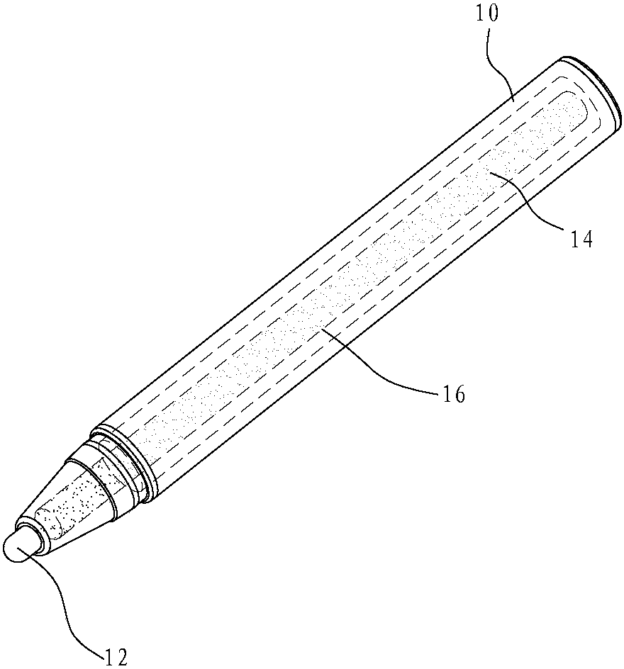
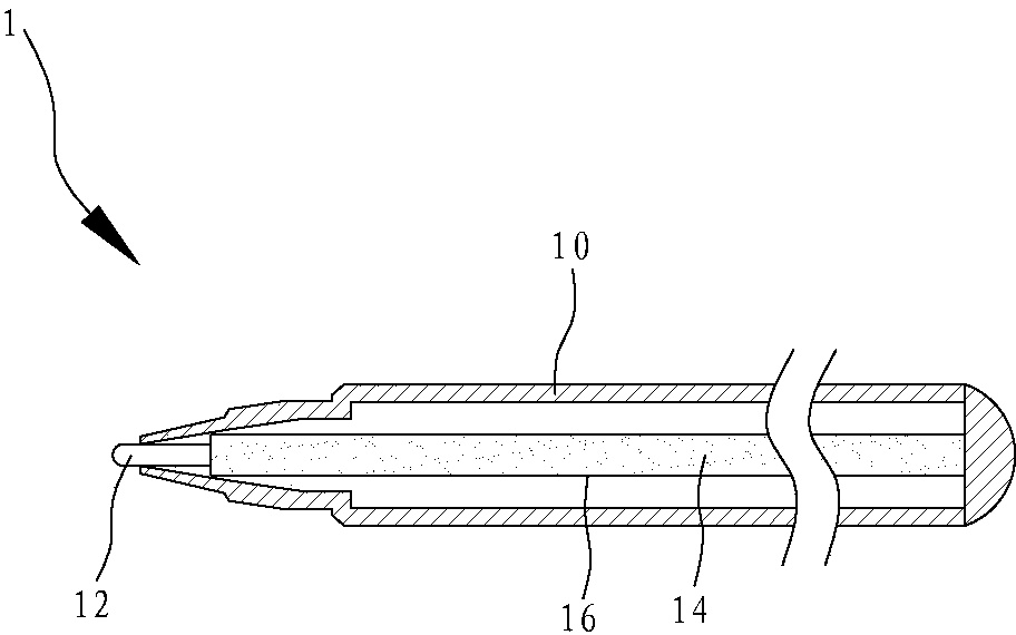
[0030] In order to further explain the technical solution of the present invention, the present invention will be described in detail below through specific examples.

[0031] see figure 1 and figure 2 As shown, it is a three-dimensional schematic diagram and a schematic cross-sectional structure diagram of a preferred embodiment of the present invention. In order to achieve the aforementioned purpose, the present invention provides an improved stylus conduction method. The stylus 1 mainly consists of a non-conductive pen body 10 and a touch head 12, wherein a refill 16 (which can be a sponge, cloth or other absorbing body with good absorbability) is placed inside the non-conductive pen body 10 to absorb a conductive agent 14, and the refill 16 can be used for adsorption conductive agent 14, and the touch head 12 is in direct contact with the refill 16, therefore, the touch head 12 can detect the capacitance change on the surface of the panel through the refill 16 adsorbed w...


PUM


Abstract

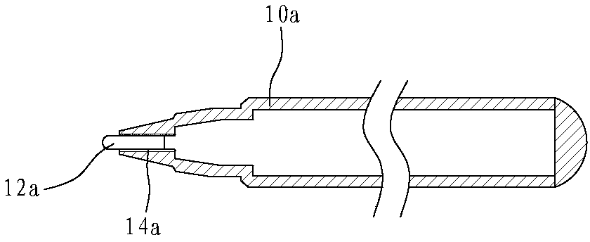
The invention relates to an improved touch pen conducting means. A touch pen mainly comprises a non-conducting pen body and a touch head, wherein a conducting agent is arranged in the non-conducting pen body, can be attached to the inner wall surface of the non-conducting pen body or a pen head end in a spraying or coating or filling way, and can also be directly filled in a cartridge in the non-conducting pen body. In any way, the touch head arranged at one end of the non-conducting pen body is enabled to be in contact with the conducting agent, so that the touch head is conductive, a panel detects the capacitance change on the surface to generate an electronic signal, and a touch position is judged. The non-conducting pen body can be directly made from colorful plastic particles, colors are plumper and more various, and secondary processing of spraying for beautification is not required, so that the cost can be reduced, and particularly, the effects of environment friendliness, energy conservation and carbon emission reduction can be achieved due to the fact that wastes are used.

Description

technical field [0001] The invention relates to a stylus, in particular to an improved conduction method of the stylus. Background technique [0002] In daily life and industrial applications, touch panels are increasingly used. They are usually installed on high-tech products such as mobile phones or tablet computers. To improve the touch effect of the panel, a stylus has been developed, which uses the conductive method of the stylus to touch the touch panel with the refill instead of touching the touch panel with fingers, thereby increasing the convenience of use. [0003] The aforementioned touch panels are mainly divided into resistive touch and capacitive touch: the resistive touch panel is composed of ITO Film and ITO Glass, separated by DOT in the middle, and connected between ITO Film and ITO Glass. A voltage of 5V is used to touch the ITO Film with a finger or an improved stylus to form a depression, and then the underlying ITO Glass contacts to generate a voltage ...

Claims


Application Information

Patent Timeline
IPC IPC(8): G06F3/0354
Inventor 吴振华
Owner 吴振华
Learn More