

Voice processing device and voice processing method
A technology of speech processing and equipment, applied in speech analysis, speech recognition, instruments, etc., can solve problems such as slow speaking, and achieve the effect of improving ease
- Summary
- Abstract
- Description
- Claims
- Application Information
AI Technical Summary
Problems solved by technology
Method used
Image

Examples
no. 1 approach )
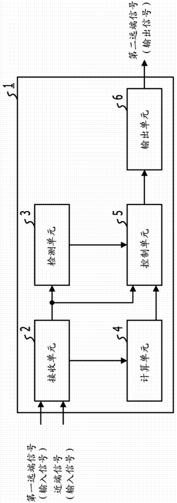
[0027] figure 2 is a functional block diagram showing the speech processing device 1 according to the embodiment. The speech processing device 1 includes a receiving unit 2 , a detecting unit 3 , a computing unit 4 , a control unit 5 and an output unit 6 .
[0028] The receiving unit 2 is realized, for example, by a wired logic hardware circuit. Alternatively, the receiving unit 2 may be a functional module realized by a computer program executed in the speech processing device 1 . The receiving unit 2 externally acquires a near-end signal transmitted from the receiving side (the user of the voice processing device 1 ) and a first far-end including an uttered voice transmitted from the transmitting side (the person communicating with the user of the voice processing device 1 ). Signal. The receiving unit 2 may receive, for example, a near-end signal from a microphone (not shown) connected to or arranged in the speech processing device 1 . The receiving unit 2 may receive ...
no. 2 approach )
[0061] exist image 3 Among them, the determination unit 7 can change the control amount (non_sp) by the adjustment amount (r_delta) according to the signal characteristic of the first remote signal. The signal characteristic of the first remote signal may be, for example, a signal-to-noise ratio (SNR) or a noise characteristic value of the first remote signal. For example, the noise feature value may be calculated in a manner similar to the way in which the calculation unit 4 calculates the noise feature value of the near-end signal. For example, the processing unit 9 may calculate the noise characteristic value of the first far-end signal, and the determination unit 7 may receive the calculated noise characteristic value from the processing unit 9 . A signal-to-noise ratio (SNR) may be calculated by the processing unit 9 using a signal-to-noise characteristic value ratio in the speech segment of the first far-end signal, and the determination unit 7 may receive the signal-t...
no. 3 approach )
[0065] exist image 3 Among them, in addition to control information #1 (ctrl-1), the generating unit 8 may generate control information #2 (ctrl-2) for controlling the speech segment length based on the speech segment length and delay. The processing performed by the generating unit 8 to generate control information #2 (ctrl-2) is described below. For the non-speech segment length, the generation unit 8 generates control information #2 (ctrl-2) such that ctrl-2=0, for example.
[0066] Please note that when ctrl-2=0, no control processing including expansion or reduction is performed on the voice segment of the first remote signal. Regarding the length of the speech segment, the generation unit 8 generates control information #2 (ctrl-2) such as ctrl-2=er, where er represents the expansion ratio of the speech segment. Note that the generation unit 8 may generate control information #2 (ctrl-2) such that ctrl-2=0 according to the delay even for the speech segment length. Th...
PUM
 Abstract
Description
Claims
Application Information