Mechanical-type steering wheel indicator

A steering wheel and indicator technology, applied in steering mechanism, transportation and packaging, vehicle parts, etc., can solve problems such as unsolvable, wrong indication, and difficulty, so as to improve ease, acceptability, and practicality of life Effect

Inactive Publication Date: 2015-10-28
马根昌
View PDF8 Cites 0 Cited by
  • Summary
  • Abstract
  • Description
  • Claims
  • Application Information

AI Technical Summary

Problems solved by technology

[0009] However, since the radius of curvature of the spiral wall 2 changes continuously, when the ball 3 approaches the center of the indicator circle, that is, in the process of moving in a direction in which the radius of curvature gradually decreases, the spiral wall 2 undergoes elastic deformation by itself. , will give the ball 3 a thrust between tangential and radial. Under the action of this thrust, the moment the steering wheel pauses, the ball 3 is likely to fly a circle in the direction of the gradually increasing radius of curvature, resulting in the indication Wrong; turn the steering wheel sharply on the bumpy road surface, as, when turning the steering wheel sharply on the parking space paved with tiles, this phenomenon is extremely obvious; The thrust formed by the elastic deformation of the spiral wall 2
[0010] For this problem, it involves many factors such as the gap size between the spiral channel and the ball, the roughness of the spiral channel, the roughness of the ball, that is, the rate of change of the radius of curvature of the spiral wall with the angle, etc. The comprehensive factors maintain a delicate balance. From the perspective of machining accuracy, it is extremely difficult and almost impossible to solve.

Method used


Image

  • Mechanical-type steering wheel indicator
  • Mechanical-type steering wheel indicator
  • Mechanical-type steering wheel indicator

Examples


Embodiment Construction

[0029] Below in conjunction with accompanying drawing and embodiment the present invention is further described:

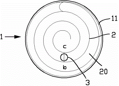
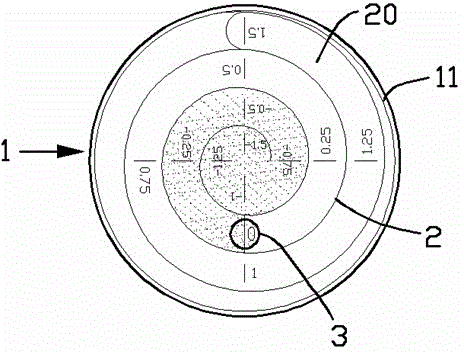
[0030] exist image 3 In the shown embodiment, the mechanical steering wheel indicator includes a cover-shaped base case 1 and a transparent panel (which may be a piece of transparent glass or resin disc, not shown) that covers the base case 1; A continuous spiral wall 2 is formed in the oblate cylindrical cavity inside the base shell 1; the planes on both sides of the spiral wall 2 are surrounded by the bottom surface of the cavity and the panels.

[0031] The spiral path of the spiral wall 2 takes the central axis of the cavity as the axis of revolution, and the outermost circle ends at the side wall 11 of the cavity.

[0032] In the spiral passage 20 formed between the bottom surface of the cavity, the spiral wall 2, and the panel, a ball 3 that can roll in the spiral passage 20 is sealed; on the bottom surface of the cavity, along The path of the spiral channe...


PUM


Abstract

The present invention provides a mechanical-type steering wheel indicator. The mechanical-type steering wheel indicator comprises a base shell and a face plate; a spiral wall is formed in a cavity inside the base shell; planes of two sides of the spiral wall are sandwiched by a bottom face and the face plate of the cavity; a spiral path of the spiral wall using a center axis of the cavity as a rotating axis, with a tail end of the outmost circle stopping at a side wall of the cavity; a rolling ball is sealed inside a spiral passage formed among the cavity bottom face, the spiral wall and the face plate and can roll inside the spiral passage; a spiral ruler is formed along the path of the spiral passage on the bottom face of the cavity, an original point of the ruler being disposed at the center of a position where the rolling ball is disposed when a steering wheel is at a returned state; and a mark indicating the angle is labeled every time the steering wheel rotates at N degrees along clockwise and anticlockwise directions of the spiral passage, with the original point being a start point, until the maximum angle by which the steering wheel can rotate along the clockwise and anticlockwise directions. With adoption of the indicator, a user can easily and naturally observe current rotating angles of the steering wheel while maintaining a clean and neat visual effect.

Description

[0001] technical field [0002] The invention relates to the field of auto parts, in particular to a steering wheel indicator. [0003] Background technique [0004] In the patent application with the application number 201320820240.7 and the patent name of the spiral wall steering wheel indicator, a structure indicating the rotation angle state of the steering wheel is proposed, roughly as figure 1 As shown, a continuous spiral wall 2 is arranged in a circular base shell 1, and the spiral wall 2 starts to radiate outward near the center of the base shell 1, and ends at the circular side wall 11 of the base shell 1; A ball 3 is limited in the spiral channel 20 formed by the spiral wall 2, so that no matter how many angles the steering wheel turns, the ball 3 is kept in a vertical direction by free rolling under the action of gravity. For example, ball 3 in figure 1 In the position shown, the base shell 1 rotates clockwise with the steering wheel for a full circle, and the...

Claims


Application Information

Patent Timeline
Patent Type & Authority Applications(China)
IPC IPC(8): B62D15/02
Inventor 马根昌
Owner 马根昌
Why Eureka
Try Eureka