Eureka AIR delivers breakthrough ideas for toughest innovation challenges, trusted by R&D personnel around the world.

Test structure and method for monitoring electricity leakage of grid electrode

A technology of test structure and test method, which is applied in the direction of semiconductor/solid-state device test/measurement, circuit, electrical components, etc., can solve the problems of reduced device yield, increased gate leakage current, residual, etc., to reduce costs and improve The effect of quality and reliability

Inactive Publication Date: 2014-06-18
SHANGHAI HUALI MICROELECTRONICS CORP
View PDF5 Cites 4 Cited by
  • Summary
  • Abstract
  • Description
  • Claims
  • Application Information

AI Technical Summary

Problems solved by technology

Therefore, when there is no via hole connection, since the pitch width between the gate and the self-aligned layer is very narrow, when the gate is photolithographically and etched, there will be residual gaps in the gate in the narrow pitch width. , the residual gate may even be short-circuited with the self-alignment layer, which will lead to an increase in the leakage current of the gate, which will cause leakage failure of the formed device in the subsequent reliability test and reduce the yield of the device
[0004] At present, there is no test structure that can well monitor the process defects described above, so that such defects are often not discovered until a very late step such as CP, FT, etc., because a large number of products have already been produced when they are discovered out, it will cause a lot of damage

Method used


Image

  • Test structure and method for monitoring electricity leakage of grid electrode
  • Test structure and method for monitoring electricity leakage of grid electrode

Examples


Embodiment Construction

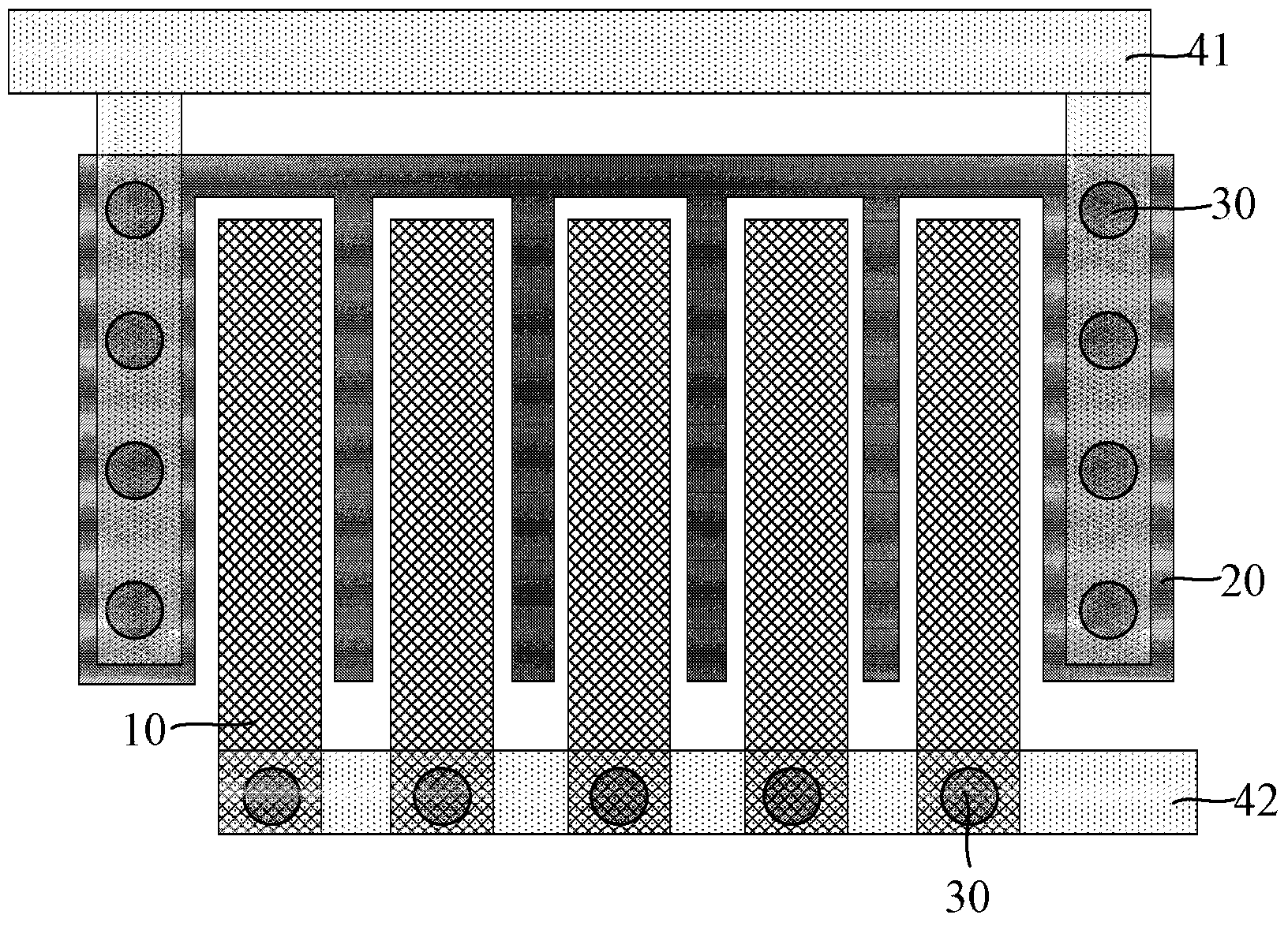
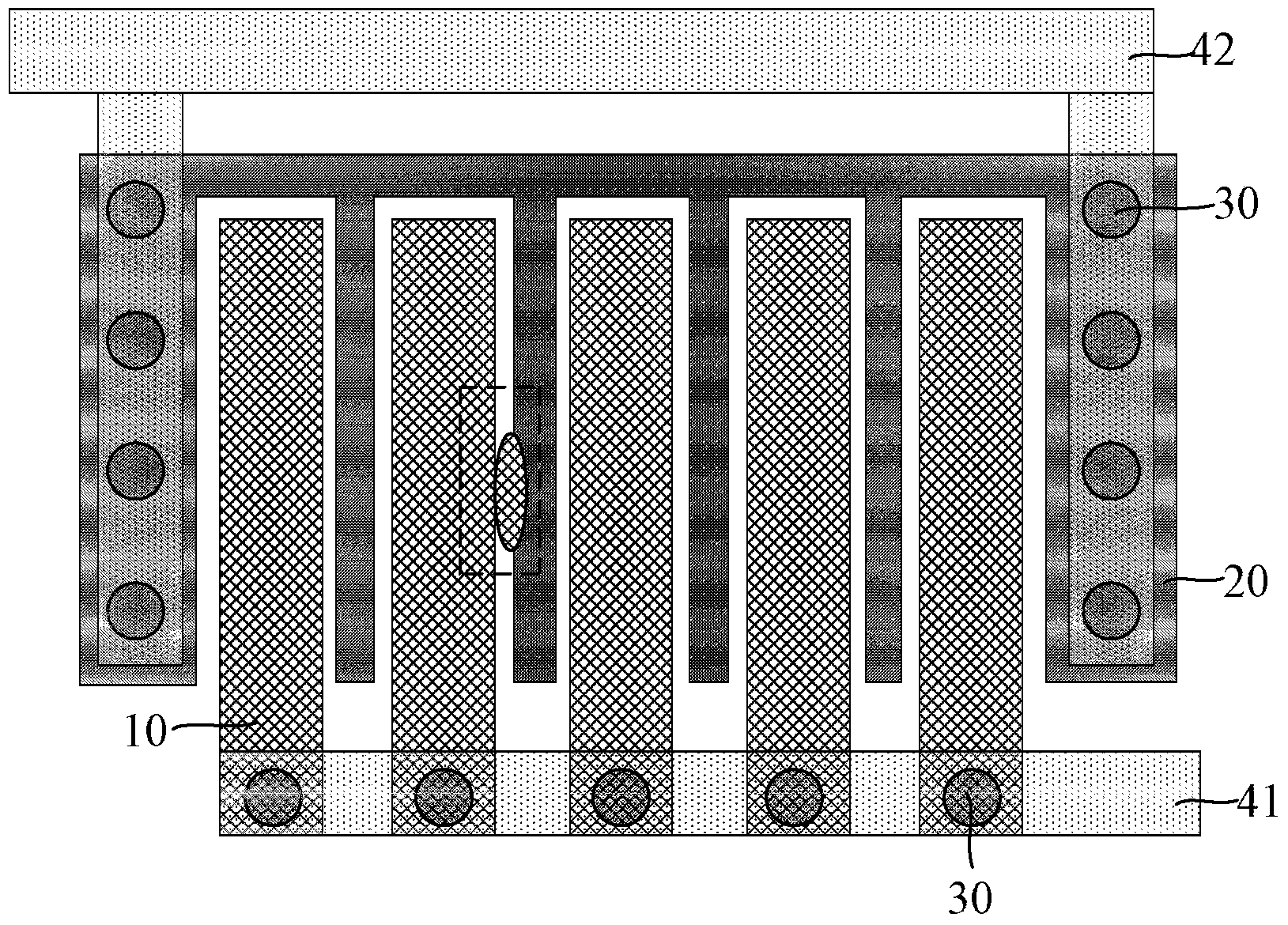
[0021] The test structure and test method for monitoring gate leakage of the present invention will be described in more detail below in conjunction with schematic diagrams, wherein a preferred embodiment of the present invention is represented, and it should be understood that those skilled in the art can modify the present invention described here, while still The advantageous effects of the present invention are realized. Therefore, the following description should be understood as the broad knowledge of those skilled in the art, but not as a limitation of the present invention.

[0022] In the interest of clarity, not all features of an actual implementation are described. In the following description, well-known functions and constructions are not described in detail since they would obscure the invention with unnecessary detail. It should be appreciated that in the development of any actual embodiment, numerous implementation details must be worked out to achieve the de...


PUM


Abstract

The invention provides a test structure and method for monitoring electricity leakage of a grid electrode. The grid electrode of a comb structure and a self-aligning layer of a comb structure are formed, are arranged in a staggered mode and are mutually isolated. In the testing process, whether the process of the grid electrode has problems can be judged by only testing whether leaked current exists between the grid electrode and the self-aligning layer, the condition of electricity leakage of the grid electrode can be tested after the grid electrode is formed, the abnormal conditions of the relevant process of the area with a narrow grid interval can be monitored rapidly in the early period, or a corresponding reliability defect can be found, and therefore the quality and reliability of products are largely improved and cost is lowered.

Description

technical field [0001] The invention relates to the field of semiconductor manufacturing, in particular to a test structure and a test method for monitoring grid leakage. Background technique [0002] Gate leakage is a problem often encountered in the design and manufacture of semiconductor integrated circuits. Most of the time it is caused by poor control of process parameters, such as the quality of the formed gate oxide layer, metal silicide process problems, front-end Process foreign particles and more. At present, some test structures such as GOI test structures have been used for conventional gate leakage monitoring. [0003] For many current layout designs, the width of the gate and the self-alignment layer (Silicide) formed on the active area (AA, ActiveArea) between the gates is not fixed. If there is a via connection (CT), Then the width between the two will be relatively large, but if there is no through hole connection (CT), the width between the two will be ve...

Claims


Application Information

Patent Timeline
Patent Type & Authority Applications(China)
IPC IPC(8): H01L21/66
CPCH01L22/14H01L22/34
Inventor 陈强
Owner SHANGHAI HUALI MICROELECTRONICS CORP
Why Eureka
Eureka Blog
Learn More