Heat radiating device of power device
A technology of power devices and heat sinks, applied in the field of communication, can solve problems such as poor insulation, high brittleness, and difficult to find cracks, and achieve the effect of improving heat dissipation
- Summary
- Abstract
- Description
- Claims
- Application Information
AI Technical Summary
Problems solved by technology
Method used
Image

Examples
Embodiment Construction
[0025] Hereinafter, the present invention will be described in detail with reference to the drawings and examples. It should be noted that, in the case of no conflict, the embodiments in the present application and the features in the embodiments can be combined with each other.
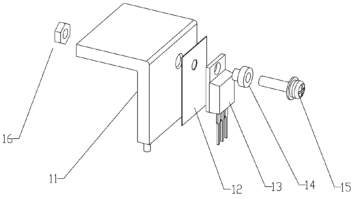
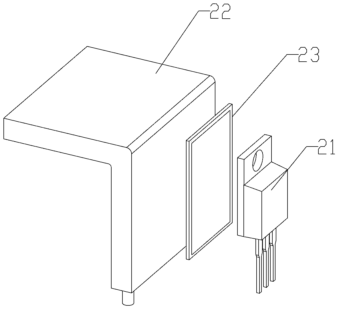
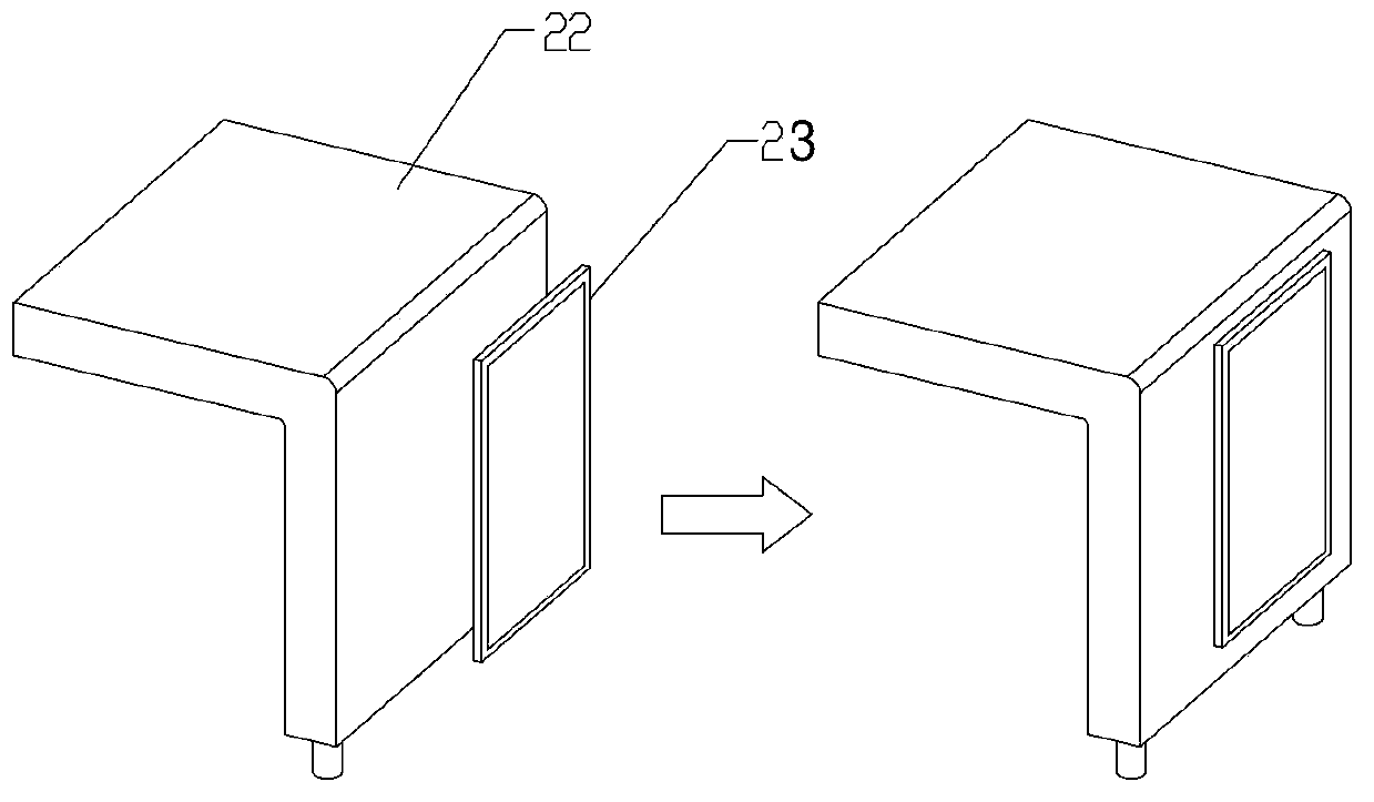
[0026] figure 2 is a schematic structural diagram of a heat dissipation device for a power device according to an embodiment of the present invention, such as figure 2 As shown, the heat dissipation device of the power device includes: a power device 21, a heat dissipation device 22, and a heat-conducting and insulating device 23 connected between the power device and the heat-dissipating device, wherein the heat-conducting and insulating device 23 is connected with the power device 21 and the heat-dissipating device 22 They are all connected by welding or bonding, and 23 pieces of thermal insulators are ceramic composite metal substrates.
[0027] In this embodiment, the heat dissipation device ...
PUM
 Abstract
Description
Claims
Application Information
 - R&D
- Intellectual Property
- Life Sciences
- Materials
- Tech Scout
- Unparalleled Data Quality
- Higher Quality Content
- 60% Fewer Hallucinations
Browse by: Latest US Patents, China's latest patents, Technical Efficacy Thesaurus, Application Domain, Technology Topic, Popular Technical Reports.
© 2025 PatSnap. All rights reserved.Legal|Privacy policy|Modern Slavery Act Transparency Statement|Sitemap|About US| Contact US: help@patsnap.com