An electronic field terminal system for power transmission engineering

A terminal system, electronic technology, applied in the direction of electrical components, cable installation, cable installation devices, etc., can solve the problems of high work intensity, high work intensity, unclear approach lines, etc., to improve work efficiency and improve work efficiency. Efficiency and time saving effect

Active Publication Date: 2017-01-11
CEEC JIANGSU ELECTRIC POWER DESIGN INST +1
View PDF3 Cites 0 Cited by
  • Summary
  • Abstract
  • Description
  • Claims
  • Application Information

AI Technical Summary

Problems solved by technology

However, the traditional transmission line design has a large workload and high work intensity, so in some aspects it is not well suited to the development direction of highly informatized and automated transmission line design, specifically in:
[0003] 1. In the field, the designer is not clear about the approach route, and needs to be familiar with the route in advance or hire a guide to guide the way. This kind of mode that relies too much on manpower is intensive and affects the work efficiency of the field.
[0004] 2. Designers need to carry a large amount of paper materials when carrying out field work. They are easily damaged in harsh weather conditions such as rainy and windy in the field, and have natural defects such as inconvenient carrying, storage, and use.
[0005] 3. The design of transmission lines requires a large number of on-site verification calculations, high work intensity, and many on-site records, requiring multi-disciplinary collaborative work
At present, this work relies on oral communication, experience judgment, and paper records. The operation process is primitive and error-prone, and work efficiency needs to be improved.

Method used


Image

  • An electronic field terminal system for power transmission engineering

Examples


Embodiment Construction

[0039] The present invention will be further described below in combination with specific embodiments.

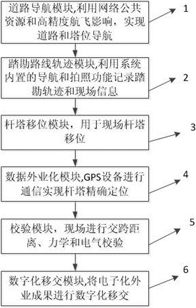
[0040] see figure 1 As shown, a power transmission engineering electronic field terminal system includes:

[0041] 1. The road navigation module, including the navigation drive unit, uses network public map resources and aerial images to realize road and tower navigation;

[0042] 2. The reconnaissance route track module, including a positioning module and a camera, is used to record the reconnaissance route track, and realize the positioning and recording of scene and location information in the system;

[0043] 3. Tower shifting module, including line plane section positioning system and geographic information system, used for on-site tower shifting;

[0044] 4. The data field module, including GPS equipment and communication module, the electronic field terminal communicates with the professional GPS equipment through the communication module, and transmits the tower ...


PUM


Abstract

The invention discloses an electronic field terminal system in a transmission project. The electronic field terminal system comprises a road navigation module, an exploration route track module, a tower displacement module, a data field module, a verification module and a digitized transfer module, wherein the road navigation module realizes road and tower position navigation by utilizing network public map resources and flying images, the exploration route track module records an exploration route track and realizes positioning records of scene and position information in the field terminal system, the tower displacement module realizes tower displacement in field, the data field module transmits tower position coordination data between GPS (global positioning system) equipment and the electronic field terminal system, the verification module carries out field crossing distance, mechanics and electrical verification, and the digitized transfer module transfers the content and achievement of field work to a local database. The electronic field terminal system has the beneficial effects that road navigation is realized, the field entering steps are simplified, the field entering time is saved, the use and the carry are convenient, information is back-up, the operation manner is improved, the field work intensity is reduced, and the working efficiency is improved.

Description

technical field [0001] The invention relates to the fields of power transmission engineering design and computers, in particular to an electronic mobile terminal system developed based on a tablet computer and suitable for field work in power transmission projects. Background technique [0002] The field work involved in the design of transmission lines includes on-site survey, on-site line selection, on-site pole arrangement, pile crossing, foundation configuration, etc. The main tasks are designers (line electrical, line structure) and surveyors (measurement, geotechnical) , hydrology) together on site. However, the traditional transmission line design has a large workload and high work intensity, so in some aspects it is not well suited to the development direction of highly informatized and automated transmission line design, specifically in: [0003] 1. Designers are not clear about the approach route in the field, so they need to familiarize themselves with the route ...

Claims


Application Information

Patent Timeline
Patent Type & Authority Patents(China)
IPC IPC(8): H02G1/00G01C21/26
Inventor 张瑞永王少宁李欣陶刚朱宇孙纯军阎平陶青松张瑞龙赵新宇马军奚海波崔君瑞崔艳军肖少辉郑博予
Owner CEEC JIANGSU ELECTRIC POWER DESIGN INST
Why Eureka
Try Eureka