
motor

A technology of electric motors and shells, applied in the field of electric motors, can solve the problem of inflexible fixed interfaces and achieve the effect of simple fixing

Active Publication Date: 2019-09-13
ROBERT BOSCH GMBH
View PDF4 Cites 0 Cited by
  • Summary
  • Abstract
  • Description
  • Claims
  • Application Information

AI Technical Summary

Problems solved by technology

With this structure, fixed interfaces are relatively inflexible and can only be adapted with corresponding financial and manufacturing expenditures

Method used


Image

  • motor
  • motor
  • motor

Examples


Embodiment Construction

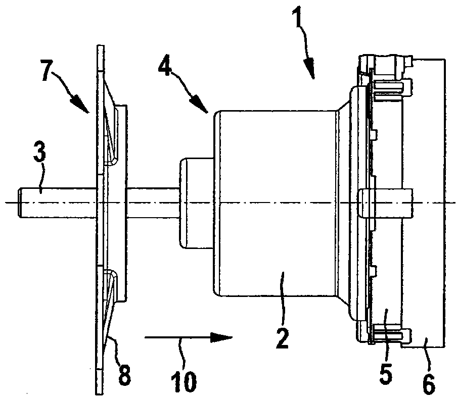
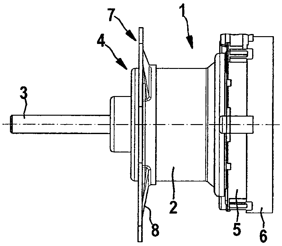
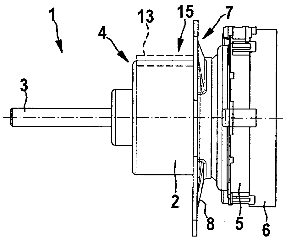
[0016] Figures 1A to 1C The electric machine 1 is shown in different assembly steps in each case in side view.

[0017] The electric machine 1 has a housing 2 in which, for example, a stator is fixedly arranged and in which a rotor is arranged rotatably mounted, wherein the rotor is connected in a rotationally fixed manner to a shaft 3 protruding radially from the housing 2 . In this case, the shaft 3 protrudes from the housing 2 at the free end 4 of the housing 2 . The end of the housing 2 opposite the free end 4 is provided with a plug connector 5 and a cover 6 , wherein the plug connector 5 is in particular held tensioned between the housing 2 and the cover 6 . The housing 2 has a circular outer contour, the outer diameter only increasing from the free end 4 to the plug 5 , but substantially constant.

[0018] The electric machine 1 also has a fastening flange 7 formed by a flange plate 8 . The flange 8 is formed as a stamped part from sheet steel and can be pushed onto ...


PUM


Abstract

The machine (1) has a mounting flange (7) arranged in a housing (2), formed as a flange plate (8) and pushed onto the housing. The flange plate is formed with a central receiving opening, where a contour of the central receiving opening is essentially formed to an outer contour of the housing. The flange plate is welded to the housing and provided with a locking element that is formed at the housing. A radial projection and a radial recess are axially extended to the housing, and the flange plate is designed as a punched and stamped part.

Description

technical field [0001] The invention relates to an electric machine, in particular an electric motor, having a housing and a fastening flange arranged on the housing. Background technique [0002] Motors of the form mentioned at the beginning are well known. Often the electric machine is fastened directly to the transmission or to another housing in order to assume the function of an electric drive and / or generator there. For this purpose, the housing is usually constructed geometrically in such a way that it has a fastening flange in which a plurality of screw openings are provided for fastening the fastening flange and thus the housing to the transmission or the Screws on other housings can be guided through the screw openings. In this case, the fastening flange is usually formed in one piece with the housing, so that, depending on the application, complex tools are required to produce the housing, with which the fastening flange and in particular the arrangement of the ...

Claims


Application Information

Patent Timeline
Patent Type & Authority Patents(China)
IPC IPC(8): H02K5/22
Inventor C·鲍尔
Owner ROBERT BOSCH GMBH
Learn More