
A control method for tailstock of CNC lathe that can realize rigid tapping

A technology of CNC lathe tailstock and CNC lathe, applied in the direction of tailstock/top, turning equipment, manufacturing tools, etc., can solve the problems of time-consuming and laborious, high processing cost, low processing efficiency, etc., to improve flexibility, eliminate no reflection To the gap, the effect of improving the degree of automation

Active Publication Date: 2018-07-06
盐城贝安特机械有限公司
View PDF9 Cites 0 Cited by
  • Summary
  • Abstract
  • Description
  • Claims
  • Application Information

AI Technical Summary

Problems solved by technology

[0002] CNC lathes are one of the most commonly used automatic processing equipment in mechanical cutting. However, the tailstock of general CNC machine tools cannot be fed automatically. Therefore, when performing tapping processes on CNC lathes, manual operations can only be performed, which is time-consuming and labor-intensive. Low, and generally only floating tapping can be used to process threaded holes, and a set of special tools is required for floating tapping, resulting in higher processing costs

Method used


Image

  • A control method for tailstock of CNC lathe that can realize rigid tapping
  • A control method for tailstock of CNC lathe that can realize rigid tapping
  • A control method for tailstock of CNC lathe that can realize rigid tapping

Examples


Embodiment Construction

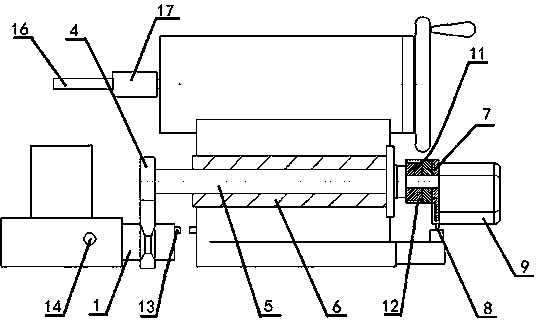
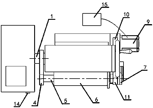
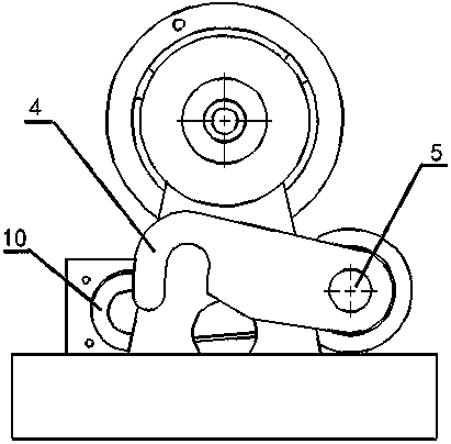
[0016] A method for controlling the tailstock of a CNC lathe that can realize rigid tapping, which uses a connecting device that uses a motor to realize the engagement and disengagement of the saddle and tailstock of the CNC lathe, including a connecting column 1, a rotating arm assembly, a driving Assemblies and tap assemblies, the middle part of the connecting column 1 is provided with an annular groove 3 with inclined surfaces on both sides, a magnetic effect sensor 2 is arranged at the groove bottom of the annular groove, and a pressure sensor 18 is arranged on each inclined surface of the annular groove , the connecting column 1 is fixedly connected with the saddle of the CNC lathe, and a pair of magnetic effect sensors 13 are arranged on the shaft end of the connecting column 1 and the side of the tailstock.

[0017] The rotating arm assembly includes a rotating arm 4, a rotating shaft 5, a shaft sleeve 6 and a limit pressure block 7, the shaft sleeve 6 is fixed on the fr...


PUM


Abstract

The invention provides a numerical control lathe tailstock control method capable of achieving rigid tapping. A connection device achieving connection and disconnection of a saddle and the tailstock of a numerical control lathe through a motor is adopted and comprises a connection column, a rotating arm assembly, a driving assembly and a screw tap assembly. The screw tap assembly is installed in a tube sleeve of the tailstock of the numerical control lathe, the middle of the connection column is provided with an annular groove with inclined faces as the two side faces, the bottom of the annular groove is provided with a sensor, the two side inclined faces of the annular groove are each provided with a pressure sensor, the connection column is fixedly connected with the saddle of the numerical control lathe, the shaft end of the connection column and the side face of the tailstock are provided with a pair of sensors, the rotating arm assembly comprises a rotating arm, a rotating shaft, a shaft sleeve and a limiting pressure block, the driving assembly comprises a pair of belt drivers, a driving motor, a reset switch and a controller, the controller is installed in a distribution cabinet of the lathe, the reset switch is installed on the front face of the saddle of the numerical control lathe, and the driving motor is fixedly connected with the tailstock of the numerical control lathe and electrically connected with the controller.

Description

technical field [0001] The application relates to the technical field of numerical control lathe control, in particular to a control method for a tailstock of a numerical control lathe capable of realizing rigid tapping. Background technique [0002] CNC lathes are one of the most commonly used automatic processing equipment in mechanical cutting. However, the tailstock of general CNC machine tools cannot be fed automatically. Therefore, when performing tapping processes on CNC lathes, manual operations can only be performed, which is time-consuming and labor-intensive. Low, and generally only floating tapping can be used to process threaded holes, and a set of special tools is required for floating tapping, resulting in higher processing costs. Contents of the invention [0003] Aiming at the existing technical defects, the present invention provides a CNC lathe tailstock automatic feed control method capable of rigid tapping function, which uses a connection device for e...

Claims


Application Information

Patent Timeline
Patent Type & Authority Patents(China)
IPC IPC(8): B23B23/00B23B25/06B23Q5/28B23Q5/50B23B43/02B23G1/18
CPCB23B23/00B23B25/06B23B43/02B23G1/18B23Q5/28B23Q5/348B23Q5/50
Inventor 冯淑珠
Owner 盐城贝安特机械有限公司
Learn More