Clutching method and device for vehicle motor and electric generator

A vehicle engine and clutch device technology, which is applied to the arrangement of multiple prime movers, power devices, circuit devices, etc. of general power devices, to achieve the effect of reducing vibration and noise when starting and stopping, and reducing damage

Active Publication Date: 2007-01-31
CSR ZHUZHOU ELECTRIC LOCOMOTIVE RES INST
View PDF0 Cites 10 Cited by
  • Summary
  • Abstract
  • Description
  • Claims
  • Application Information

AI Technical Summary

Problems solved by technology

During this period, the starter is in the maximum load area for a long time, and may malfunction due to excessive heat

Method used


Image

  • Clutching method and device for vehicle motor and electric generator
  • Clutching method and device for vehicle motor and electric generator

Examples


Embodiment 1

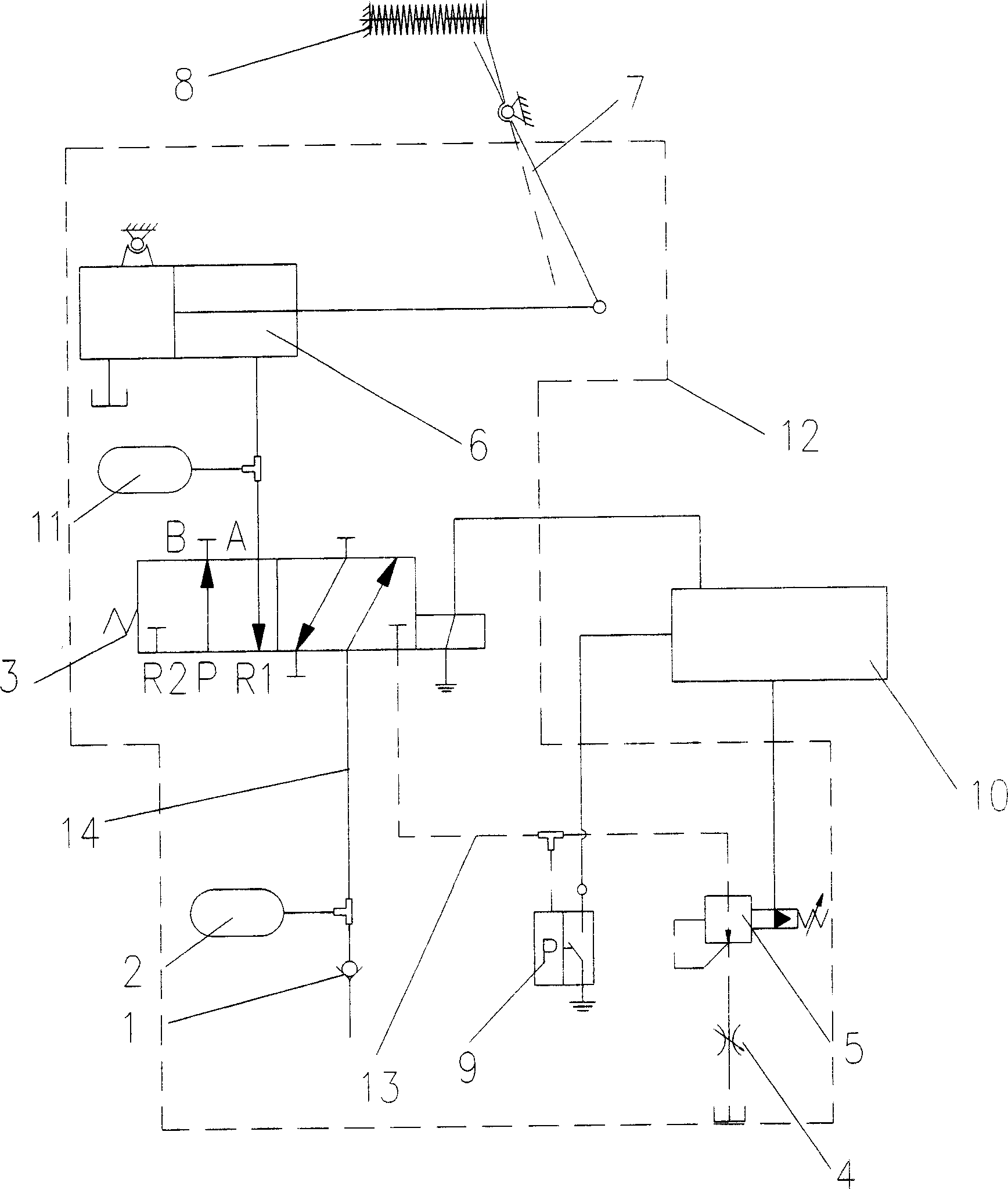
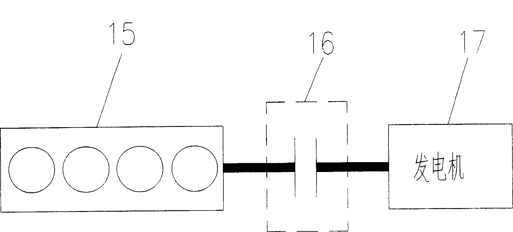
[0015] The utility model relates to a clutch device between an engine and a generator, including the engine and the generator. There is a clutch device between the engine and the generator, and the clutch device is an electronically controlled pneumatic device. The clutch device is an electronically controlled pneumatic clutch device, which uses a friction disc clutch transmission mechanism, a pneumatic operating mechanism and a microcomputer control system to realize the engagement or separation of the engine and generator. The whole system includes two parts: a clutch execution part and a control part. The clutch execution part is a conventional friction plate clutch 8 , and the control part includes a microcomputer control system 10 and a pneumatic operating mechanism 12 . The clutch 8 is connected with a pneumatic operating mechanism 12 , and the pneumatic operating mechanism 12 is controlled by a microcomputer control system 10 . The pneumatic operating mechanism 12 is a ...

Embodiment 2

[0029] A clutch device between an engine and a generator, including the engine and a generator, is characterized in that there is a clutch device between the engine and the generator, and the clutch device is an electronically controlled hydraulic clutch device, the principle of which is the same as that of Embodiment 1 It is the same, the whole clutch device is divided into two parts, the clutch execution part and the control part. The hydraulic operating mechanism is a hydraulic driving mechanism, the driving cylinder is a hydraulic driving cylinder; the control circuit is a hydraulic circuit.

Embodiment 3

[0031] A clutch device between an engine and a generator, including the engine and a generator, is characterized in that there is a clutch device between the engine and the generator, and the clutch device is a mechanical manual clutch device. The whole clutch device is divided into two parts, the clutch execution part and the control part, wherein the clutch execution part is mainly composed of a friction disc clutch transmission mechanism; the control part is a manual operation mechanism, and the friction disc clutch is directly operated manually agency manipulated.


PUM


Abstract

The present invention relates to an engagement and disengagement method for vehicle engine and power generator and its device. Between the engine and power generator an engagement and disengagement device is set, said device can be used for making engine and power generator implement combination or separation. Said device can be electrically-controlled pneumatic device, also can be electrically-controlled hydraulic engagement and disengagement device, also can be mechanical manual engagement and disengagement device. It includes two portions of engagement and disengagement execution portion and control portion.

Description

technical field [0001] The invention relates to a clutch method and device for a vehicle engine and a generator, in particular to an electronically controlled clutch method and device for a gasoline / diesel generator set and a serial hybrid vehicle generator set. It is mostly used in the APU system of gasoline / diesel generator sets and series hybrid vehicles. Background technique [0002] In traditional gasoline / diesel generator sets and the APU system of series hybrid electric vehicles, the engine and generator are usually installed directly. However, the generator itself has a certain moment of inertia, which is generally about twice the moment of inertia of the engine. In this way, the direct-connected installation of the generator will have the following adverse effects on the starting of the engine: [0003] ——If starting at the same time (same acceleration), then: the maximum torque of the starter motor needs to be increased by 2 times; then the size of the engine and ...

Claims


Application Information

Patent Timeline
Patent Type & Authority Applications(China)
IPC IPC(8): B60K6/02H02J7/14F01B23/10B60K6/38
CPCY02T10/7005Y02T10/70
Inventor 席力克
Owner CSR ZHUZHOU ELECTRIC LOCOMOTIVE RES INST
Why Eureka
Try Eureka