A kind of signal detection method and equipment of pucch
A signal detection and signal power technology, applied in wireless communication, digital transmission system, electrical components, etc., can solve the problem of unable to detect PUCCH format3 signal
- Summary
- Abstract
- Description
- Claims
- Application Information
AI Technical Summary
Problems solved by technology
Method used
Image
Examples
Embodiment 1
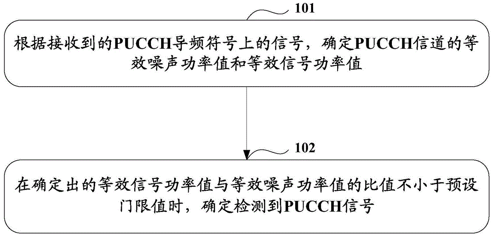
[0091] Such as figure 1 As shown, the PUCCH signal detection method in Embodiment 1 of the present invention includes the following steps:
[0092] Step 101: Determine an equivalent noise power value and an equivalent signal power value of the PUCCH channel according to the received signal on the PUCCH pilot symbol.
[0093] Step 102: When the determined ratio of the equivalent signal power value to the equivalent noise power value is not less than a preset threshold value, determine that a PUCCH signal is detected.
[0094] Wherein, step 101 can be realized through the following steps:
[0095] Step 1: For a receiving antenna, determine the frequency domain corresponding to the pilot symbol and the transmitting port according to the signal sequence on each PUCCH pilot symbol received on the receiving antenna and the pilot base sequence corresponding to each transmitting port Pilot channel estimation sequence.
[0096] Step 2: converting each frequency-domain pilot channel ...
Embodiment 2
[0246] Embodiment 2 is a kind of network side device belonging to the same inventive concept as Embodiment 1. Therefore, the implementation of Embodiment 2 may refer to the implementation of Embodiment 1, and repeated descriptions will not be repeated.
[0247] Such as figure 2 As shown, the equipment of this embodiment includes:
[0248] The first determination module 21 is used to determine the equivalent noise power value and the equivalent signal power value of the PUCCH channel according to the signal on the received PUCCH pilot symbol;
[0249] The second determining module 22 is configured to determine that a PUCCH signal is detected when the ratio of the equivalent signal power value determined by the first determining module 21 to the equivalent noise power value is not less than a preset threshold value.
[0250] Preferably, the first determination module 21 is specifically used for:
[0251] For a receiving antenna, according to the signal sequence on each PUCCH ...
Embodiment 3
[0288] Embodiment 3 is a kind of network side device belonging to the same inventive concept as Embodiment 1. Therefore, the implementation of Embodiment 2 may refer to the implementation of Embodiment 1, and repeated descriptions will not be repeated.
[0289] Such as image 3 As shown, the equipment of this embodiment includes:
[0290] The processor 300 is configured to determine the equivalent noise power value and the equivalent signal power value of the PUCCH channel according to the signal on the PUCCH pilot symbol received by the transceiver 310; after the determined equivalent signal power value and the equivalent When the ratio of the noise power value is not less than the preset threshold value, it is determined that the PUCCH signal is detected;
[0291] The transceiver 310 is used for receiving and sending data under the control of the processor 300 .
[0292] Preferably, the processor 300 is specifically used for:
[0293] For a receiving antenna, according to...
PUM
 Abstract
Description
Claims
Application Information
 - R&D
- Intellectual Property
- Life Sciences
- Materials
- Tech Scout
- Unparalleled Data Quality
- Higher Quality Content
- 60% Fewer Hallucinations
Browse by: Latest US Patents, China's latest patents, Technical Efficacy Thesaurus, Application Domain, Technology Topic, Popular Technical Reports.
© 2025 PatSnap. All rights reserved.Legal|Privacy policy|Modern Slavery Act Transparency Statement|Sitemap|About US| Contact US: help@patsnap.com


