
Fine particle emission reduction device of burning energy system based on acoustic agglomeration principle

An energy system, a technology for fine particulate matter, applied in auxiliary pretreatment, dispersed particle separation, chemical instruments and methods, etc., can solve the problems of limited emission reduction effect and scale, low sound field intensity, etc.

Active Publication Date: 2014-06-25
NAT UNIV OF DEFENSE TECH
View PDF7 Cites 17 Cited by
  • Summary
  • Abstract
  • Description
  • Claims
  • Application Information

AI Technical Summary

Problems solved by technology

The semi-industrial scale system with the highest published power produces only 1600W (Rodriguez J J, et al. Acoustic agglomeration for electrostatic retention of fly-ashes at pilot scale: influence of intensity of sound field at different conditions. Journal of aerosol science, 1996,21:621-622), the sound field intensity is not high, and the emission reduction effect and scale are limited

Method used


Image

  • Fine particle emission reduction device of burning energy system based on acoustic agglomeration principle
  • Fine particle emission reduction device of burning energy system based on acoustic agglomeration principle
  • Fine particle emission reduction device of burning energy system based on acoustic agglomeration principle

Examples


Embodiment Construction

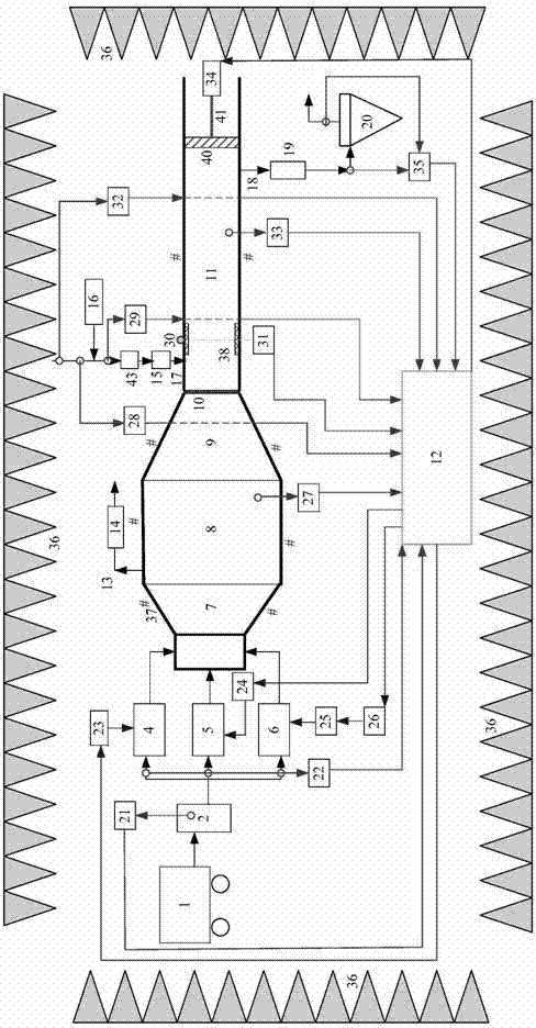
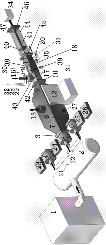
[0057] The working principle of the emission reduction device of the present invention is combined with figure 1 A brief description is as follows:

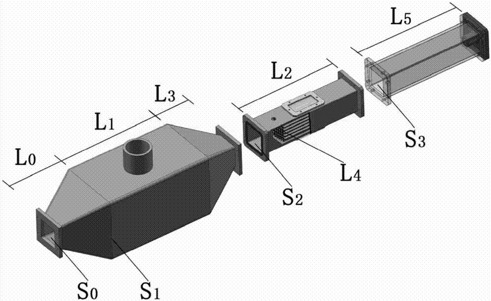
[0058] The high-pressure airflow provided by the high-pressure airflow source 1 (air compressor or high-pressure air supply source) enters the high-pressure air mixing chamber 2. After the pressure of the high-pressure airflow is stabilized in the high-pressure air mixing chamber, it is selected to enter the high-pressure cyclone according to the determined optimal working condition. Flute 4, resonant type strong sound generator 5 or modulated airflow sound source 6, in the above-mentioned airflow sound source, the high-pressure airflow energy is converted into strong sound waves; the strong sound waves pass through the horn 7 (the horn-shaped line can be straight, hyperbolic or exponential) Line) enters the cross-sectional section 8 of the coupling cabin and the contraction section 9 of the coupling cabin, passes through the so...


PUM

PropertyMeasurementUnit
Wall thicknessaaaaaaaaaa
Thicknessaaaaaaaaaa

Abstract

The invention designs a device for realizing acoustic agglomeration emission reduction of fine particles in high-flow flue gas of a burning energy system. The device comprises a high-pressure gas flow source, a high-pressure gas mixing chamber, gas flow sound sources, a horn, a coupling cabin, an agglomeration cabin, an extended cabin, a movable end surface, a conventional dust remover, a data sensing control part, a central measurement and control computer, a sound elimination part and a sound insulation part. According to the device, the three high-power gas flow sound sources are matched with a variable-section pipeline by fully utilizing the principle that the acoustic agglomeration efficiency is sharply improved along with the increment of the sound pressure level; a barrier structure and a gas-sound separation part are introduced, so that the fine particles are quickly agglomerated in the large-size agglomeration cabin under the action of a high-strength and low-harmonic-component planar standing wave sound field; running parameters are adjusted and optimized in a unified manner by virtue of the measurement and control computer; the best transmission efficiency of strong sound waves from generating to acting is realized and the characteristic change of the fine particles is adapted; the whole realization scheme has the advantages of emission reduction efficiency, economical efficiency, applicability, no pollution, extendability and the like.

Description

technical field [0001] The invention relates to an emission reduction device for removing fine particulate matter (hereinafter referred to as PM2.5) with a particle size of less than 2.5 microns in flue gas discharged from a combustion energy system, in particular to a fine particulate matter emission reduction device based on the principle of acoustic coagulation, belonging to The technical field of pollution control equipment manufacturing. Background technique [0002] With the rapid development of my country's economy, the consumption of energy is increasing, and the pollutants discharged into the atmosphere by chemical combustion energy systems are increasing. In recent years, according to the environmental monitoring data of major and medium-sized cities, PM2.5 serious exceeding the standard has occurred from time to time, and urban smog has repeatedly appeared in a large area. These all show that fine particulate matter mainly PM2.5 has become the main pollutant of u...

Claims


Application Information

Patent Timeline
IPC IPC(8): B01D51/08
Inventor 曾新吾赵云龚昌超田章福吴学利
Owner NAT UNIV OF DEFENSE TECH
Learn More