Water-skipper-imitation waterborne skipping robot
A robot and water strider technology, applied in the field of bionic robots, can solve problems such as the inability to achieve continuous jumping motion on water
- Summary
- Abstract
- Description
- Claims
- Application Information
AI Technical Summary
Problems solved by technology
Method used
Image
Examples
specific Embodiment approach 1
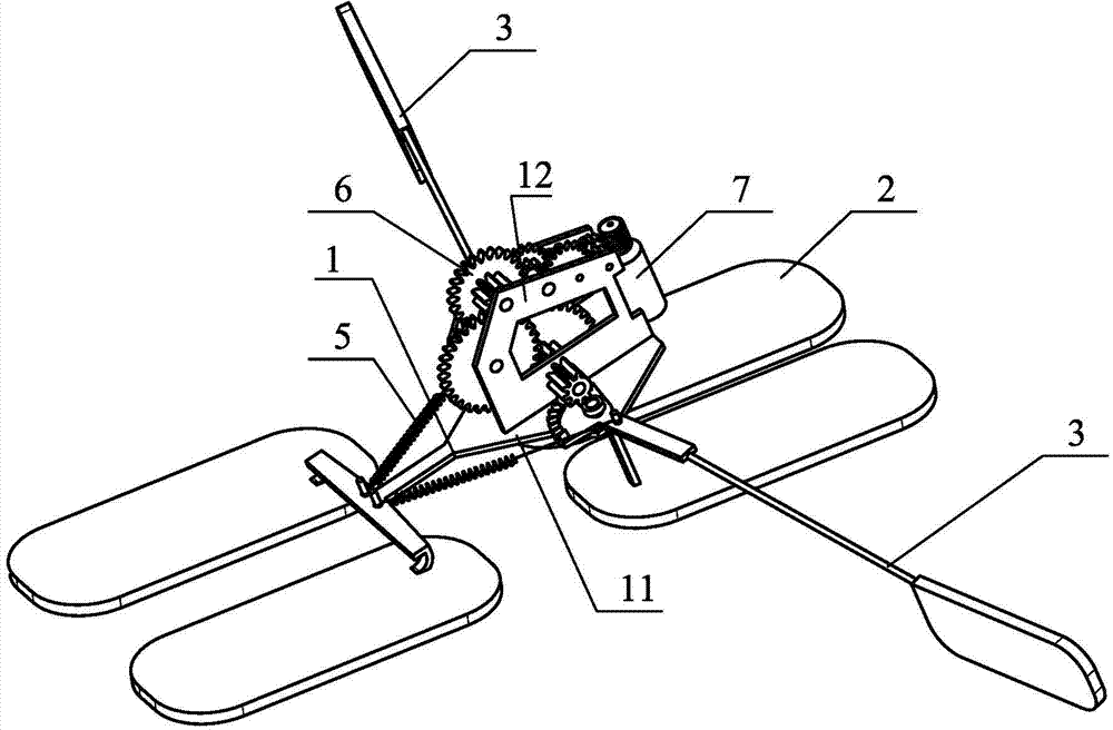
[0014] Specific implementation mode one: combine figure 1 and figure 2 Describe this embodiment, the imitation water strider water jumping robot in this embodiment, it comprises frame 1, four support legs 2, two driving legs 3, two springs 5, reduction gear set 6, miniature DC motor 7 and control Circuit, the frame 1 is composed of a base 11 and a reduction gear set fixed frame 12 fixed on the upper surface of the base 11, the four supporting legs 2 are located on the same horizontal plane and are respectively bonded to the lower surface of the base 11, the Two drive legs 3 are symmetrically installed on the left and right sides of the reduction gear set fixed frame 12, and each drive leg 3 includes an incomplete gear 1 31, a connecting rod 32 and a paddle 33, an incomplete gear 1 31 and a paddle 33 Respectively bonded to the two ends of the connecting rod 32, the two driving legs 3 mesh with the reduction gear set 6 through two incomplete gears 31 respectively, and the two ...
specific Embodiment approach 2
[0016] Specific implementation mode two: combination image 3 , Figure 4 To illustrate this embodiment, the reduction gear set 6 includes multiple sets of cooperatingly installed gears and shafts, specifically: gear one 62 and shaft one 91, gear two 63 and shaft two 92, gear three 64 and shaft three 93, gear four 65 and shaft two Axis 4 94, gear 5 66 and shaft 5 95, incomplete gear 2 67, incomplete gear 3 68, gear 6 69 and shaft 6 96; gear 1 62, gear 2 63, gear 3 64, gear 4 65, gear 5 66 and gear six 69 are double-layer gears, specifically including a pair of coaxially connected large gears and pinion gears, the large teeth of the worm 61 and gear one 62 form a worm gear, and the transmission ratio is 16:1; the small gear of gear one 62 The teeth mesh with the large teeth of gear two 63, and the transmission ratio is 3:1; the small teeth of gear two 63 mesh with the large teeth of gear three 64, and the transmission ratio is 9:4; the small teeth of gear three 64 and gear fou...
specific Embodiment approach 3
[0017] Specific implementation mode three: combination figure 1 To illustrate this embodiment, the base 11 in this embodiment is fixed with shaft seven 97, shaft eight 98, shaft nine 99, shaft ten 910, shaft eleven 911 and shaft twelve 912, incomplete gear two 67, incomplete gear Gear three 68 meshes with two incomplete gears one 31 respectively, and the openings of two incomplete gears one 31 respectively cooperate with shaft seven 97 and shaft eight 98 in clearance and are provided with a shaft stopper 101 which acts as a limit and fixation at the opening; The seventh axis 97 and the eighth axis 98 are tightly fitted and fixed with the corresponding openings on the frame 1 respectively; the ninth axis 99 and the tenth axis 910 are respectively tightly fitted and fixed with the corresponding openings on the two driving legs 3; the eleventh axis 911 and the twelve 912 are closely fitted and fixed with the corresponding openings on the frame 1 respectively. Other compositions ...
PUM
 Abstract
Description
Claims
Application Information
 - R&D
- Intellectual Property
- Life Sciences
- Materials
- Tech Scout
- Unparalleled Data Quality
- Higher Quality Content
- 60% Fewer Hallucinations
Browse by: Latest US Patents, China's latest patents, Technical Efficacy Thesaurus, Application Domain, Technology Topic, Popular Technical Reports.
© 2025 PatSnap. All rights reserved.Legal|Privacy policy|Modern Slavery Act Transparency Statement|Sitemap|About US| Contact US: help@patsnap.com


