Clamping mechanism of electrical pipeline lift

A clamping mechanism and lifter technology, which is applied in the field of lifts, can solve problems such as easy loosening of the clamping device, reduced service life of the lifter, and damage to the lifting part, so as to increase the force, reduce the degree of damage, and reduce the effect force effect

Inactive Publication Date: 2014-06-25
SHOUGUANG JUNENG ELECTRIC
View PDF6 Cites 3 Cited by
  • Summary
  • Abstract
  • Description
  • Claims
  • Application Information

AI Technical Summary

Problems solved by technology

[0003] However, in small and medium-sized load-carrying screw elevators, when the motor fails or the power is cut off, the lifting part of the elevator will suddenly fall, which will cause a large impact force between the lifting part and the supporting part, which is easy to cause lifting. Part of the interior is damaged, which reduces the service life of the elevator; during the lifting process of the pipe fittings, the pipe fittings are vertically lifted and lowered according to the needs, and the pipe fittings are clamped by the clamping device of the lifting part. It is prone to loosening, which will cause the pipe fitting to slide down and the outer surface of the pipe fitting will rub against the clamping device during the sliding process, resulting in damage to the pipe fitting

Method used


Image

  • Clamping mechanism of electrical pipeline lift

Examples


Embodiment

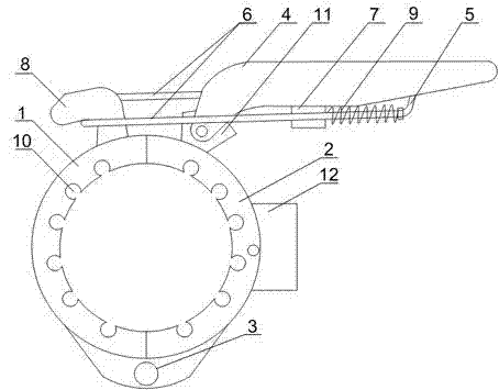
[0021] Such as figure 1 As shown, a clamping mechanism of an electric pipeline lifter in the present invention includes a left snap ring 1 and a right snap ring 2, the left snap ring 1 is connected to the right snap ring 2 through a pin shaft 3, and the right snap ring 2 The upper part is equipped with a handle 4, and both sides of the handle 4 are provided with protrusions 7, and a pressure rod 5 is also installed on the handle 4, and the two ends of the pressure rod 5 are connected with a hanging rod 6, and the upper part of the left snap ring 1 Hanging ears 8 are installed, and the hanging rod 6 passes through the protrusion 7 and cooperates with the hanging ear 8 to fix the left snap ring 1 and the right snap ring 2. On the hanging rod 6, a spring 9 is also arranged and the spring 9 is located on the protrusion 7. Between the pressure rod 5; on the inner wall of the ring formed by the left snap ring 1 and the right snap ring 2, a plurality of superior arc grooves 10 are ar...


PUM


Abstract

The invention discloses a clamping mechanism of an electrical pipeline lift. The clamping mechanism comprises a left clamping ring and a right clamping ring, and the left clamping ring is connected with the right clamping ring through a hinge pin. A handle is arranged on the upper portion of the right clamping ring, protrusions are arranged on the two sides of the handle, the handle is further provided with a pressing rod, the two ends of the pressing rod are connected with hanging rods, the upper portion of the left clamping ring is provided with hanging lugs, the hanging rods penetrate through the protrusions and are matched with the hanging lugs to enable the left clamping ring and the right clamping ring to be fixedly connected, and the hanging rods are further provided with a spring located between the protrusions and the pressing rod. In the clamping process, connection between the left clamping ring and the right clamping ring is adjusted through the spring. When a lifting portion swings obviously, the compressed spring keeps acting force between the pressing rod and the protrusions at any time, the clamping strength on a pipe fitting is guaranteed, and the pipe fitting is prevented from slipping downwards in the swinging process; meanwhile, relative sliding friction between the pipe fitting and the left clamping ring and relative sliding friction between the pipe fitting and the right clamping ring are avoided, and the damage degree of the pipe fitting is reduced.

Description

technical field [0001] The invention relates to a lift, in particular to a clamping mechanism of an electric pipeline lift. Background technique [0002] The traditional screw jack is generally composed of worm gear, box, bearing, screw and other parts; the working principle is: the motor or manual drive the worm to rotate, the worm drives the worm gear to decelerate the rotation, the inner cavity of the worm gear is processed into an internal thread, and drives the screw up and down Moving, due to the worm gear and worm inside, the deceleration effect of the lead screw achieves the effect of amplifying the thrust. As a kind of modern lifting equipment, the screw elevator has a wide range of applications, and the development of the screw elevator is also very rapid. It is not difficult to draw the development direction of the elevator in the future. Among them, the speed, variable speed and safety performance are the key points, and the importance of safety It is very impor...

Claims


Application Information

Patent Timeline
Patent Type & Authority Applications(China)
IPC IPC(8): B66F17/00F16B7/10
Inventor 陈怀之王刚聂海涛张仁友胡国波
Owner SHOUGUANG JUNENG ELECTRIC
Why Eureka
Try Eureka