
Cantilever beam slippage system for self-elevating drilling platform

A drilling platform and cantilever beam technology, which is applied in hydraulic engineering, artificial islands, underwater structures, etc., can solve the problems of high labor intensity, low work efficiency, and affecting sliding efficiency.

Active Publication Date: 2014-06-25
SICHUAN HONGHUA PETROLEUM EQUIP
View PDF6 Cites 5 Cited by
  • Summary
  • Abstract
  • Description
  • Claims
  • Application Information

AI Technical Summary

Problems solved by technology

However, the traditional cantilever beam sliding system has the following problems: the synchronization of the cantilever beam movement cannot be well guaranteed, which seriously affects the sliding efficiency; Quickly deal with various emergencies, especially when the pump set is overloaded or other components are damaged during skid start, it cannot be responded quickly
Although this can make it easier for the pin to be inserted into the round hole of the cantilever beam, the pin can only transmit force in one direction. When the cantilever beam changes direction, it is necessary to manually exchange the semi-cylindrical surface and the inclined cone surface of the pin, which is labor-intensive and efficient. Low

Method used


Image

  • Cantilever beam slippage system for self-elevating drilling platform
  • Cantilever beam slippage system for self-elevating drilling platform
  • Cantilever beam slippage system for self-elevating drilling platform

Examples


Embodiment Construction

[0057] The present invention will be further described in detail below in conjunction with examples and specific implementation methods. However, it should not be understood that the scope of the above-mentioned themes of the present invention is limited to the following embodiments, and all technologies realized based on the contents of the present invention belong to the scope of the present invention.

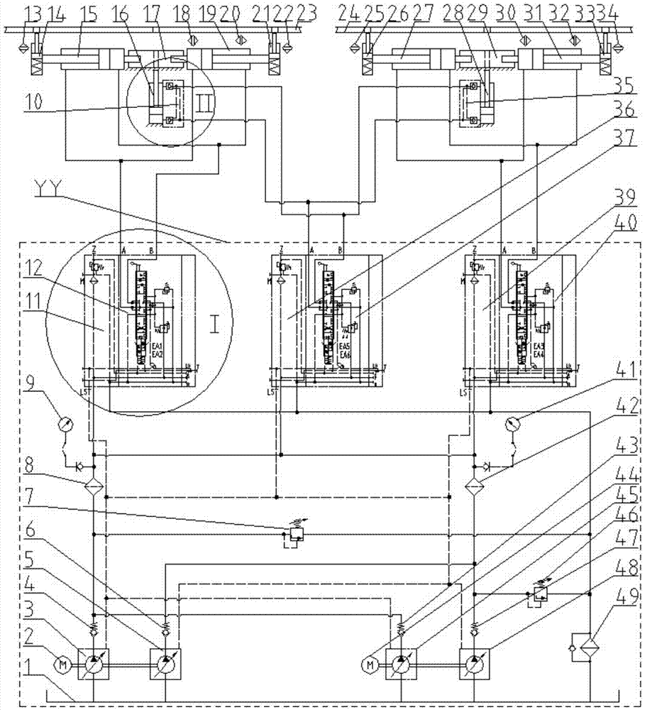
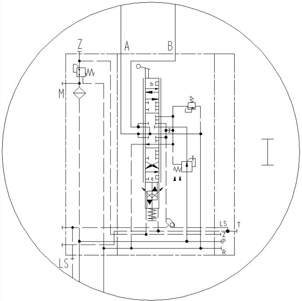
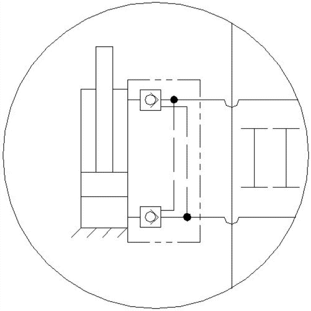
[0058] Such as figure 1 As shown, the cantilever beam sliding system of this embodiment includes a double pump group P, a control valve group K, a hydraulic actuator Z, a sliding device H, a hydraulic pipeline assembly G, a valve F, an instrument Y, and an oil source 1 and hydraulic station YY.

[0059] Wherein, the double pump group P includes the first double pump group P1 and the second double pump group P2; the control valve group K includes the first control valve group K1, the second control valve group K2 and the third control valve group K3; The hydraulic actuator ...


PUM


Abstract

The invention discloses a cantilever beam slippage system for a self-elevating drilling platform. The cantilever beam slippage system comprises at least two hydraulic execution components distributed at the symmetric positions of the two sides of a cantilever beam, control valve sets matched with the hydraulic execution components and connected with the corresponding hydraulic execution components, a hydraulic pipeline assembly connected with the hydraulic execution components and the control valve sets, a power unit, a valve, an instrument and an oil source, wherein the power unit, the valve, the instrument and the oil source are installed in the hydraulic pipeline assembly and used for controlling and achieving work of the hydraulic execution components. The power unit comprises at least two double pump sets, and the double pump sets are backups for each other. According to the cantilever beam slippage system, eccentric loading of the execution components on the two sides of the cantilever beam does not occur, the cantilever beam moves, returns and slips smoothly, the phenomenon that the cantilever beam is twisted and getting stuck due to eccentric loading and can not be compensated does not occur, and the double pump sets can be started to drive the cantilever beam to slip and be started under the condition of the maximum starting static friction force .

Description

technical field [0001] The invention relates to the technical field of offshore oil drilling platform equipment, in particular to a cantilever beam sliding system of a jack-up drilling platform. Background technique [0002] At present, jack-up drilling platforms are mainly used for offshore oil and natural gas drilling. When drilling cluster wells, in order to save drilling costs, the cantilever beam of the jack-up drilling platform needs to carry and move the drilling rig to different designated positions. The cantilever beam sliding system is one of the three core systems of the jack-up drilling platform. During oil and natural gas drilling operations, the traditional cantilever beam needs to be slid longitudinally to the outside of the ship and accurately positioned and locked at the designated position. The drilling rig can slide and lock laterally on the cantilever beam. The drilling rig can drill multiple wells horizontally at different vertical designated positions...

Claims


Application Information

Patent Timeline
Patent Type & Authority Applications(China)
IPC IPC(8): E02B17/00
Inventor 路道庆张廷忠张泽
Owner SICHUAN HONGHUA PETROLEUM EQUIP
Learn More