Enclosed loading framework for multidimensional bearing test on large-scale structural member
A technology for large-scale structural parts and loading frames, which is used in the testing of machine/structural parts, the testing of mechanical parts, measuring devices, etc. It can solve problems such as inability to ensure safety, improve measurement accuracy, reduce measurement errors, and reduce deformation. Effect
- Summary
- Abstract
- Description
- Claims
- Application Information
AI Technical Summary
Problems solved by technology
Method used
Image

Examples
Embodiment Construction
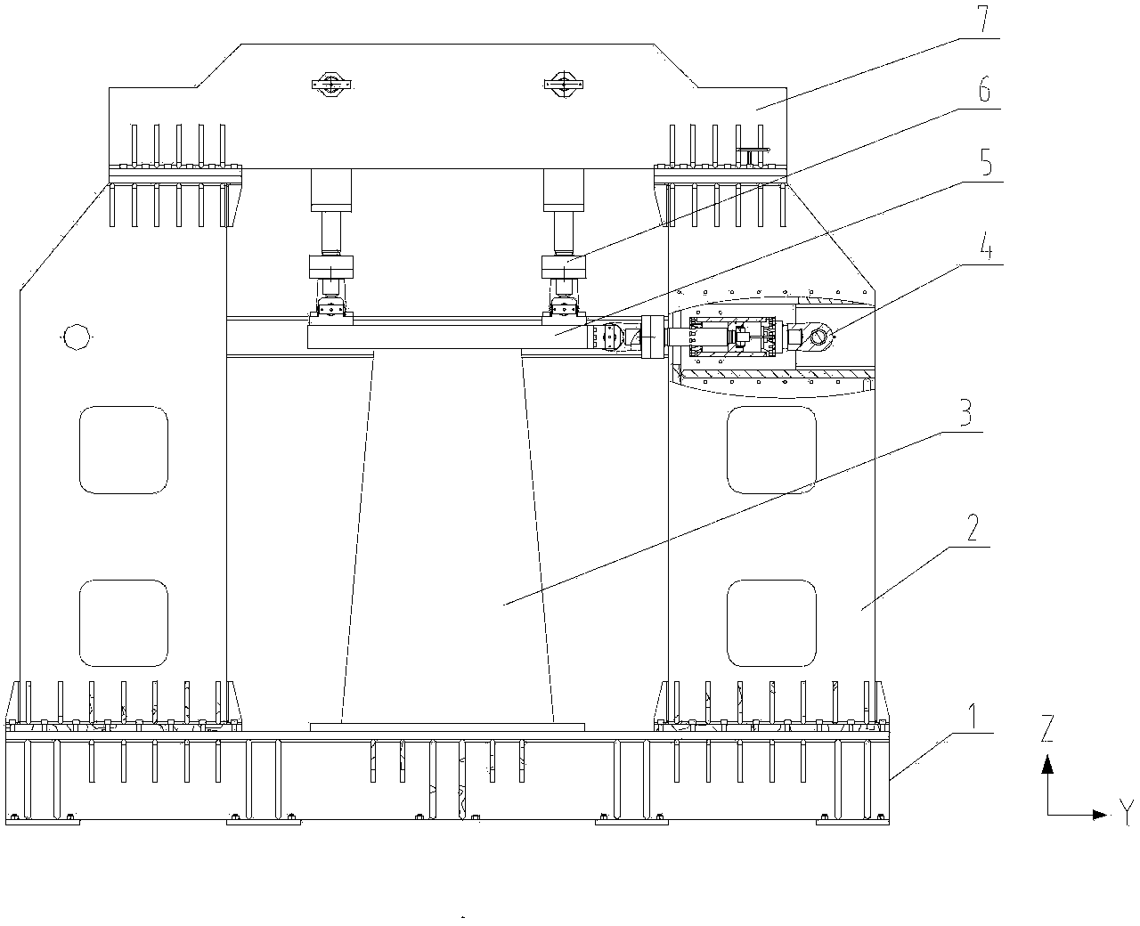
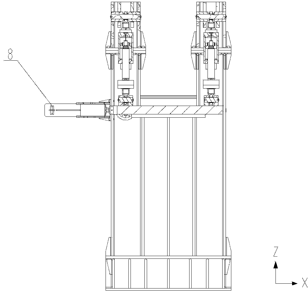
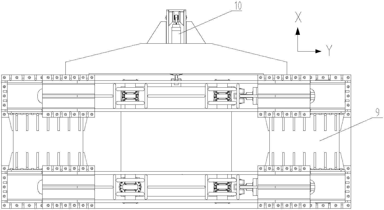
[0013] Such as figure 1 , 2 , 3, the closed frame is composed of a rigid base 1, four columns 2, a rear beam 8, an upper beam 7, a load loading plate 5, an oil cylinder and the like. Equipped with multiple hydraulic cylinders in the X, Y, and Z directions as force-applying mechanisms. Rigid base 1, four columns 2, rear beam 8, and upper beam 7 are all welded with steel plates, and then connected with bolts to form a closed frame. The uprights 2 are fixed to the rigid base 1 with bolts. The load loading plate 5 is connected with the sample 3 to be tested.
[0014] The rigid base 1 is connected with four columns 2 by bolts. The left two columns 2 in the front view are bolted together by a column connecting beam 9, and the right two columns 2 in the front view are also connected together by a column connecting beam 9 with bolts. The upper beam 7 is connected with four columns 2 with bolts. Rear beam 8 is connected together with two upright columns 2 left and right in the fr...
PUM
 Abstract
Description
Claims
Application Information